


7
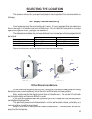
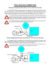
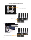
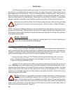
Dual Unit Connection
For some larger pools, it may be nec-
essary to install two units in parallel. In this
case, double the distances recommanded in
the table 1 of the page 5. Never place two MP
models coil against coil, fan against fan or coil
against fan.
1,2 and 3 : calibrated valves
4 : filter
5 : water pump
6 : flow meters
5
3
4
2
1
6
6
When the access to a heat pump is shut off, the water flow passing through this heat
pump will be redistributed among all others. Therefore, the valves mus be re-ad-
justed to meet the water flow requirements.
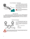
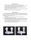
Salt Chlorinator
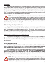
In-line Chlorinator or Brominator
The in-line chlorinator or brominator
should be installed on the pool water return line,
between the heat pump and the pool. This type
of chlorinator (brominator) should be installed
as far as possible from the heat pump. Install a
check-valve between the heat pump and the
chlorinator (brominator).
The p-trap should be installed higher than
the top of the chlorinator (brominator) to
prevent migration.
P-trap
Water pump
Chlorinator
Filter
Check-valve
Salt chlorinators are made to be installed like in-line chlorinators. Therefore, they must
be installed in accordance with the “In-line Chlorinator or Brominator” connection di-
rectives, else the warranty of the heat pump will be voided. (See the section “Water Main-
tenance” on p.12 and the section «Salt Generated Chlorine» on p.15 for more information on
operating salt chlorinators.)