


BIL-JAX 3522A
28
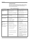
TROUBLESHOOTING
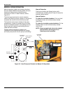
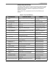
Refer to Table 4-1 for basic troubleshooting operations. Additional information
can be found in the Bil-Jax Model 3522A Parts and Service Manual. Contact the
Bil-Jax Service Department with any questions or before attempting any
advanced troubleshooting operations.
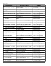
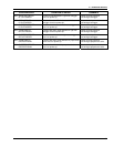
Table 4-1. Troubleshooting Steps
PROBLEM CAUSE SOLUTION
No lights on panel when
key switch is turned to the
on position.
a. Emergency STOP engaged.
b. Battery charge is low.
c. Battery ground or in-series cable is loose.
d. Battery main disconnect unplugged.
a. Disengage Emergency STOP buttons.
b. Recharge as needed.
c. Inspect and repair battery connections.
d. Plug in main disconnect.
Hydraulic function does not
work and display window
shows an error message
a. Fault detected by safety interlock
microprocessor.
b. Boom Lift electric or electronic failure
a. Refer to Table 4-2 for error code
definition and correction.
b. Refer to Table 4-2 for error code
definition and correction.
Outrigger indicator LED
lights do not function.
a. Key switch turned to the OFF or platform
controls position.
b. Emergency
STOP engaged.
c. Outriggers not deployed.
a. Turn key switch to ground controls
position.
b. Disengage emergency STOP buttons.
c. Deploy all outriggers.
One or more boom controls
do not function
OR
One or more boom controls
function improperly
OR
One or more boom controls
function intermittently.
a. Key switch is turned to the OFF or
incorrect control position.
b. Battery charge is low.
c. Emergency
STOP engaged.
d. Battery ground or in-series cable loose.
e. All outriggers not properly deployed.
f. Hydraulic pump inoperative.
g. Loose wiring connector.
h. Valve solenoid not operating properly.
i. Fault detected by system interlock.
j. Broken or loose wire.
a. Turn key switch to ground or platform
controls position.
b. Recharge battery.
c. Disengage Emergency STOP buttons.
d. Inspect and repair battery connections.
e. Deploy all outriggers and level boom lift.
f. Inspect pump; replace or repair as
needed.
g. Check wiring terminals in control box
and at valve manifold; replace or repair
as needed.
h. Clean valve solenoid and recheck
function(s); replace or repair as needed.
i. Check display for system status. Refer
to Table 4-2 for error code definitions
and correction.
j. Inspect wiring in control box and at
valve manifold and valve coil; repair or
replace as needed.