


BIL-JAX 3522A
NORMAL OPERATING PROCEDURE
Perform the following procedures to operate the Bil-
Jax Model 3522A Articulating Boom Lift.
Read and obey all safety precautions and
operating instructions, as well as all applicable
portions of ANSI A92.2, reprinted in Section 6.
Position the boom lift at the work area. Make
sure the boom lift is on a firm and level surface
and there are no potential hazards such as
overhead obstructions or electrically charged
conductors. Do not operate the boom lift if such
hazards exist.
Inspect the boom lift for damaged or worn parts.
Repair or replace parts as necessary. Never
operate a damaged boom lift.
Apply the boom lift parking brake or chock the
wheels.
Lower the tongue jack and unhitch the boom lift
from the tow vehicle.
WARNING
Failing to unhitch the boom lift before operation
may lead to damage to equipment or tow vehicle
and makes the boom lift unstable, which can
cause personnel injury or death.
18
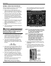
Turn the key switch on the ground control station
to operate ground controls. If power does not
come on, make sure both emergency
STOP
buttons (ground and platform) are pulled out and
the main power disconnect is plugged in.
The control microprocessor will perform self-
diagnostics to test the operating system. After
several seconds, the DISPLAY PANEL window
will read:
BIL – JAX
A STEP ABOVE
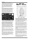
Verify that the control status indicator LED is lit.
If the control status indicator LED is not lit or is
flashing, the outrigger buttons will not work. A
flashing control status LED indicates that one or
more of the booms is raised and needs to be
stowed. Refer to Figure 3-1 and Figure 3-3.
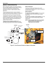
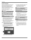
Extend the outriggers manually or using the
AUTO LEVEL button. When the boom is leveled
properly, a buzzer will sound and two LEDs at
each
OUTRIGGER button and the LED at the AUTO
LEVEL
button will be lit.
Auto Level: Press and hold the
EXTEND and
AUTO LEVEL
buttons at the same time.
Manual Level: Extend the two outriggers
closest to the trailer coupler first. Lower each
pair of outriggers by pressing the
EXTEND button
and the two appropriate
OUTRIGGER buttons at
the same time.
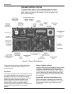
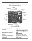
Figure 3-3. Outrigger Controls
NOTE: The safety interlock system prevents all
boom operations if the boom is not level
or if one or more outriggers are not
supporting the vehicle load.
NOTE: The Range of Motion Diagrams at the
ground and platform control stations
display the range of platform motion
(safe operating zone) facing away from
the trailer tongue. Verify that the
operating zone is clear of obstructions
through 700º of turntable rotation.
Verify that the auto level indicator LED is lit. If
the auto level indicator is not lit, the boom may
not be level.
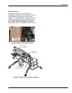
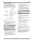
On both the upper and lower booms, pull the
latch release on the boom travel latch, raise the
latch handle and swing the latch U-bolt down.
Refer to figure 3-4.
Figure 3-4. Boom Travel Latch