25
SERVICE INSTRUCTIONS
groove should be smooth as should the rest of the fl at
surface.
The bore for the shaft seal should be smooth or oil leakage
may occur.
GEAR HOUSING
Shake the gear housing and the two seal check balls (not
shown) should rattle. If the seal balls do not rattle then
they are probably plugged with contaminants and the gear
housing will require replacement.
SHAFTS
The shaft diameter at the bearing and seal locations must
be smooth. Grooves, roughness or a reduced diameter
indicate fl uid contamination or damaged bushings. Grit
particles may have been imbedded in the bushings grind-
ing into the hardened shaft. If abnormal shaft wear as
above occurs (more than normal polishing), replace both
the shaft and associated bushings.
Also check the hydraulic system for excess contamination
in the fl uid and for fi lter condition. Operating conditions
may require changing from a 25-micron fi lter to an over-
sized 10-micron fi lter.
MOTOR REASSEMBLY
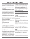
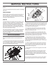
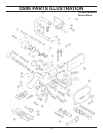
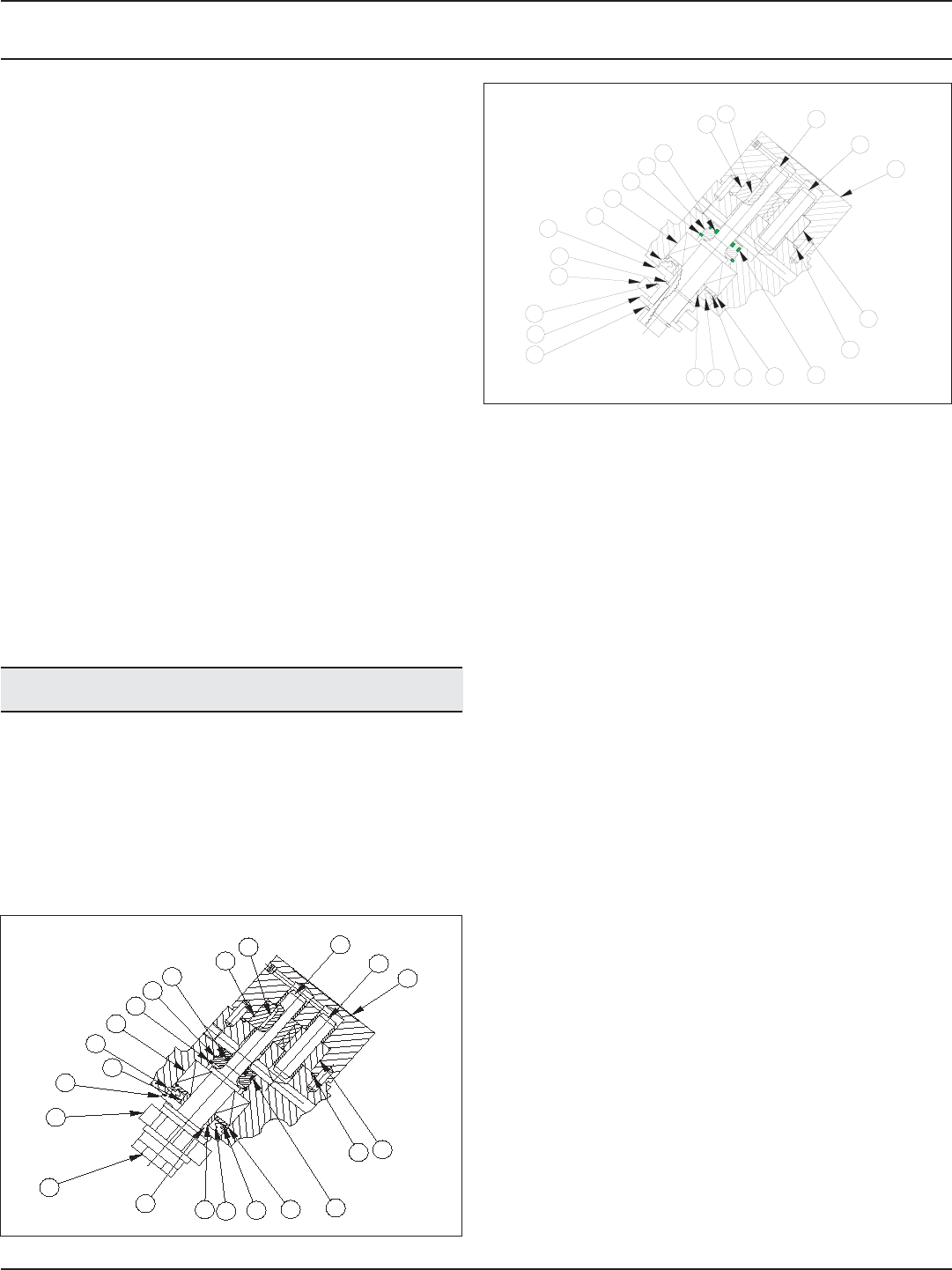
Refer to the illustration below for correct placement of
parts.
1. If the bushings (6) were removed from the valve handle
(22) and the gear housing (4), install new bushings using
a p/n 11918 bearing pusher. (NOTE: The bushing split line
must face the center of the gear housing).
2. Grease and carefully install a new quad ring (90) into the
seal liner (57). Grease and install a new o-ring (56) onto the
seal liner. Install the seal liner into the valve handle assy
(22). Replace the retaining ring (91).
3. To replace the bearing (92) onto the motor shaft (53),
support the bearing inner race and press the motor shaft
through the bearing inner race.
4. Place the valve handle assy on a smooth clean arbor
press surface (protected from damage) with the large bear-
ing bore facing up. Position the valve handle so a clearance
hole exists for the insertion of the motor shaft.
5. Apply grease to the motor shaft, keyway and bush-
ing and then insert the motor shaft through the shaft seal.
Using a socket with a diameter equal to the bearing O.D.,
press the bearing and motor shaft into place. Press only on
the outer race.
6. Install the needle roller (54) in the keyway of the motor
shaft. Use grease to keep the needle roller in place. Slide
the drive gear (13) over the needle roller and shaft. Install
the idler shaft (8) and gear (9).
7. Apply grease to the face seal o-ring groove; then install
the o-ring (7).
8. Note the screw hole pattern on the rear gear housing
and the valve handle. They will only assemble one way.
With all parts aligned, carefully slide the gear housing as-
sembly over the gears until it contacts the valve handle. Do
not force parts together.
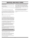
9. Turn the motor shaft manually to check for free rotation.
Install the eight capscrews (1) and then recheck rotation.
60
49
58
48
100
47
98
92
91
57
90
13
54
53
8
4
7
56
93
94
95
96
9
Serial Number 357 and Above.
97
95
94
93
56
49
48
47
98
92
90
57
91
4
8
53
54
13
96
9
7
100
Serial Number 356 and Below.


