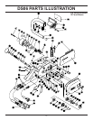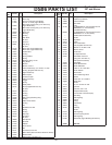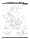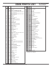
23
SERVICE INSTRUCTIONS
PRIOR TO DISASSEMBLY
Clean exterior of the tool.
Obtain a seal kit so that all seals exposed during disas-
sembly can be replaced.
ON-OFF VALVE SERVICING
TRIGGER (28) AND SAFETY CATCH (30)
REMOVAL & INSTALLATION
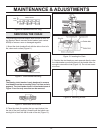
1. Drive the roll pins (20) out of the handle assembly using
a 3/16 in./4 mm diameter punch. Press the safety latch and
remove the trigger (28).
NOTE: The safety catch can be removed at this time by
driving out the 3/16 inch roll pin (21), but this is not neces-
sary for servicing the on-off valve.
2. To install the trigger and safety catch reverse the above
procedures.
VALVE SPOOL (14) REMOVAL &
INSTALLATION
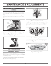
1. Remove the plug button (19) from the top of the handle
by prying under the edge and then pulling it from the
handle.
2. Drive the roll pins (20) out of the handle assembly using
a 3/16 in./4 mm diameter punch. Press the safety latch and
remove the trigger (28).
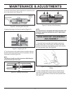
3. Drive the roll pin (20) (holding the valve spool (14) in
place) out of the handle using a 3/16 in./4 mm diameter
punch.
4. Unscrew the seal cap (44) and remove it, the spring
(42), and the steel ball (41).
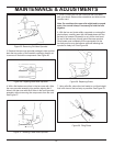
5. Lift out the valve spool assy (14 thru 18).
6. Using a 1/2 in./12.7 mm diameter wood dowel, place the
dowel into the valve spool bore from the plug button (19)
end of the handle. Push the dowel against the water valve
sleeve (38) to push the water sleeve out.
REASSEMBLY
1. Inspect the spool bore of the handle and the outer
surfaces of the spool for damage. Some light surface
scratches will be noticeable. Grooves, roughness or
a reduced diameter indicate fl uid contamination. If
abnormal wear is present (more than normal polishing),
replace both the spool and the handle.
2. Apply grease and install a new o-ring (15) onto the ON/
OFF valve (14).
3. Apply grease and install new o-rings (34 & 35) into the
spool bore of the handle.
4. Apply grease and install new o-rings (37 & 39) onto the
water valve sleeve (38).
5. If the spring retainers (16) and spring (17) were removed
from the ON/OFF valve, reinstall them. Lubricate the ON/
OFF valve with hydraulic fl uid and install it into the valve
handle. Secure it in place with the roll pin (20).
6. Install the water valve sleeve into the valve handle.
7. Install the push pin (40), steel ball (41), spring (42), and
seal cap (44). Make sure a new o-ring (43) is installed onto
the seal cap.
8. Install the safety catch (30) making sure the spring (29)
is positioned properly. Make sure the pin (33) is in place.
Secure the safety catch with the roll pin (21).
9. Install the trigger (28) and secure with the roll pin (20).
10. Replace the plug button (19) and test the action of the
safety catch and trigger.
FLOW CONTROL
Note:
Diamond saws with a serial number of 357 and above,
no longer require a fl ow control.
The fl ow control (32) is factory preset and is not fi eld ser-
viceable. Use the following as guides to check for proper
regulated fl ow.
For 5 gpm model:
If the regulated fl ow is over 6.6 gpm or under 5.4 gpm at 8
gpm input, the fl ow control valve should be replaced.
For 8 gpm model:
If the regulated fl ow is over 10 gpm or under 8 gpm at 12
gpm input, the fl ow control valve should be replaced.


