


7
SECTION 1 – ASSEMBLY INSTRUCTIONS
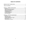
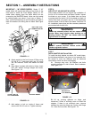
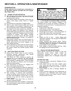
IMPORTANT – “M” SERIES RIDERS: Series 17, “M”
model riders will require the drilling of two holes in the
front frame to install the Front Weight. Series 19, “M”
model riders already have the holes drilled but are
covered by the SNAPPER decal. Holes can be located
by rubbing lightly over decal. If you have a Series 17
rider, use the dimensions on the illustration provided to
mark the locations for drilling the two holes. See Figure
1.11.
FIGURE 1.11
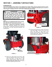
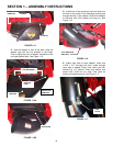
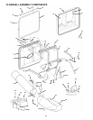
A. Attach weight to the front frame of Rider using
(2) 3/8-16 x 3” hex head bolts and (4) heavy
3/8” flat washers. Place one washer on each
bolt.
B. Align holes in weight with holes in frame. Insert
bolt, with washer, through weight and frame.
See Figure 1.12.
FIGURE 1.12
C. Add washer to bolt on inside of frame and
secure with 3/8-16 Lock nut. Tighten securely.
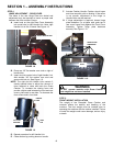
STEP 6
AIR LIFT KIT, #6-0480 INSTALLATION
Some Rider models will not require the installation of
the Air Lift Kit included with the Grass Catcher. Inspect
the blade on your mower. If the blade does not have
mounting holes for the Air Lift Kit, the blade is a High Lift
version and does not require the kit. If the blade does
have the holes in the lift area of the blade, install the Lift
Kit. Installation instructions and the necessary hardware
are included with the Air Lifts.
WARNING
Blades are extremely sharp and can cause severe
injuries. Wear heavy gloves when working on or
handling blades. DO NOT use blades that show
signs of wear or damage.
WARNING
DO NOT operate machine without entire Grass
Catcher or guards in place.
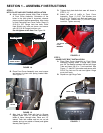
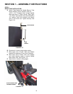
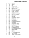
STEP 7
DECK ADAPTER INSTALLATION
To install the deck adapter on certain 28” model riders,
the discharge deflector may have to be removed first.
Be careful to save the deflector and all hardware
removed for future use when not bagging.
A. Remove wing nuts, flat washers and bolts
securing deflector to side of deck. Save hardware.
See Figure 1.13.
FIGURE 1.13
B. Lift up, pivoting deflector on hinge, and
determine if there is sufficient room to install the
adapter. If there is not sufficient room, remove
deflector by removing Hinge nut, Spring, and Hinge
Pin. Save for future use. See Figure 1.14.
DRILL TWO 13/32”
DIAMETER HOLES
2-5/8”
10”
3”
FRONT WEIGHT3/8-16X3” BOLT &
3/8” FLATWASHER
WING NUTS &
FLAT WASHERS