


5
SECTION 1 – ASSEMBLY INSTRUCTIONS
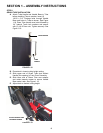
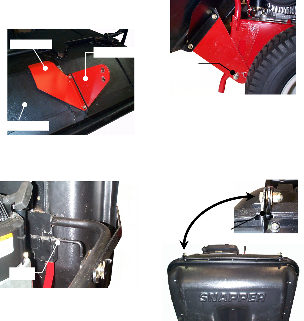
STEP 2
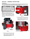
HITCH PLATE AND HEAT SHIELD INSTALLATION
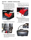
A. Attach triangular shaped Hitch Plate to bottom
of Front Cover Assembly. Orientation of the
holes in the hitch plate is important, observe
picture carefully before assembling. Align holes
in Hitch Plate and Front Cover Frame. Insert (2)
5/16-18 x 5/8” Flange Lock hex bolts. Place
Heat Shield over bolts as shown and secure
with (2) 5/16-18 Flange Lock hex nuts.
Do not tighten at this time. See Figure 1.4.
FIGURE 1.4
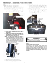
B. Place Front Cover Assembly over rear bumper
and secure in place with spring loaded latch.
See Figure 1.5.
FIGURE 1.5
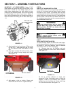
C. Align hole in Hitch Plate with hole in Bumper
Support. Insert 1/2-13 x 1” hex bolt, with head on
inside of frame, through holes. Place one 1/2”
Internal Tooth lock washer and hex nut on bolt
(washer and nut on outside of frame) and tighten
securely. See Figure 1.6.
D. Tighten hitch plate bolts that were left loose in
STEP 2, “A”.
E. Attach left end of baffle to Front Cover
Assembly. Place (1) 3/16” Flat Washer over
#10-24 x 3/4” Flange Lock Bolt and insert from
inside cover. Secure with (1) #10-24 Flange
Lock Nut. Tighten securely.
FIGURE 1.6
STEP 3
HINGE PIVOT BOLT INSTALLATION
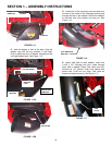
A. Place Rear Cover Assembly on Front Cover
Assembly aligning holes in hinge tabs. Place
one 3/8” flat washer between the two left Hinge
Tabs and insert 3/8-16 x 1” hex head bolt. See
Figure 1.7. Add 3/8” flat washer and secure with
3/8-16 Top Lock nut. Do not over tighten. Hinge
must pivot freely.
B. Repeat on right Hinge Tabs.
FIGURE 1.7
HEAT SHIELD
HITCH PLATE
FRONT COVER
LATCH
1/2” NUT &
LOCK
WASHER
HINGE TAB