


6
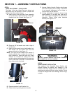
SECTION 1 – ASSEMBLY INSTRUCTIONS
STEP 4
HINGE ADJUSTMENT – REAR COVER
The holes in the rear Hinge Plate are slotted and
adjustment may be required to insure a proper seal
between the front and rear Covers.
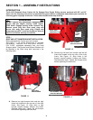
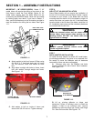
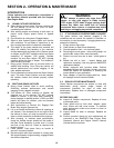
A. Insert hook on the right Rear Cover Assembly
into round hole in right Handle Link. Note: right
Handle Link is flat, no bend. See Figure 1.8.
FIGURE 1.8
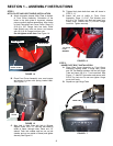
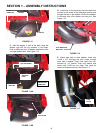
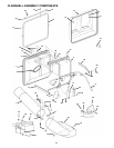
B. Place one 3/8” flat washer over stud on right of
handle tube.
C. Insert stud into center hole of right Handle Link.
Add another 3/8” flat washer over stud and
secure with hair pin. See Figure 1.9.
NOTE: The right and left Handle Links contain 3
closely spaced holes to adjust the amount of
force required to close and latch the Grass
Catcher. To increase the closing force and
provide a tighter seal between the front and rear
covers, place stud in rear hole. To decrease the
force, place stud in front hole.
FIGURE 1.9
D. Repeat procedure for left Handle Link.
E. Close catcher by pushing down on handle.
F. Actuate Catcher Handle. Catcher should open
and close smoothly with no binding. If the action
is not smooth, adjustment to the Hinge or
Handle Links may be required.
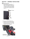
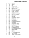
G. If hinge adjustment is required, loosen hinge
plate hardware. For a tighter seal, push top of
rear cover frame firmly against the Front Cover
Assembly. Tighten hinge plate hardware
securely. See Figure 1.10.
FIGURE 1.10
WARNING
DO NOT operate machine with Grass Catcher if
front weight has not been installed.
STEP 5
FRONT WEIGHT INSTALLATION
The weight of the Clamshell Grass Catcher and
contents affects the stability and handling of the
machine. The front weight must be installed prior to
operating the machine with the catcher installed. Failure
to install the weight could cause damage, serious injury
or death.
HOOK
RIGHT HANDLE LINK
HINGE PLATE
HARDWARE
PUSH
HANDLE
LIN
K
HAIR
PIN
3/8” FLAT
WASHER