


35
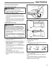
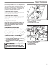
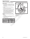
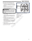
Figure 32. Parking Brake Adjustment (RH Side
Shown)
A. Brake Linkage Bar
B. Adjustment Nut
C. Rear Bumper Bar
D. Linkage Tab
E. Adjustment Jam Nut
F. Clevis Jam Nut
G. Clevis
H. Set Collar
I. Brake Shaft
J. Brake Spring
C
D
A
1/8”
(0,32 cm)
2-5/8”
(6,7 cm)
I
H
G
J
B
E
F
S/N: 2014999630 & Above:
Adjusting the Cable Placement
1. Disengage the PTO, stop the engine, block the
front wheels, remove the ignition key and engage
the parking brake.
2. Chock the wheels to prevent movement.
3. Disengage the parking brake.
4. Locate the brake linkage bar (A, Figure 32)
underneath the back of the machine. Make sure
that the clevis is flush with the end of the cable
thread with the parking brake disengaged and the
tabs (D) should contact the rear bumper bar (C).
5. Remove the clevis pin and cotter pin.
6. Using the 9/16” nuts, adjust the cable placement
in the engine deck until the hole in the clevis is
aligned with the hole in the shaft.
7. Lock the 9/16” nuts.
8. If necessary, turn the clevis until the clevis pin
slides easily in the hole.
9. Instal the pin and secure with the cotter pin.
10. Tighten the jam nut.
Adjusting the Parking Brake Springs
1. Engage the parking brake.
2. Loosen the set collar (H, Figure 32) on the front of
the brake shaft (I).
3. Locate the brake springs (J) underneath the rear
of the machine.
4. With the parking brake engaged, measure the
compressed spring length. The spring should
be 2-5/8” (6,7 cm) ± 1-1/16” (.15 cm) when
compressed.
5. If the spring length does not equal the
measurement, the spring length will need to be
adjusted.
6. There are three nuts on the linkage rod (C). The
first two (B & E) are to be used together to adjust
the spring length and the third (F) towards the rear
of the machine is used to lock the linkage rod in
place.
7. Loosen the adjustment jam nut (E) from the
adjustment nut (B).
8. Turn the adjustment nut to change the length of
the spring.
9. Tighten the adjustment jam nut against the
adjustment nut.
10. Engage the parking brake and re-measure
CAUTION
Do not adjust the spring to be shorter than
2-1/2“ (6,35 cm) when compressed. This may
damage the brake mechanism.
the spring. Continue this process until the
compressed spring length measures 2-5/8” (6,7
cm) +/- 1/8” (.32 cm).
11. Once the measurement is achieved, check to
make sure the clevis jam nut (F) is tight against
the clevis (D). If not, tighten the clevis jam nut
against the clevis.
12. Position the set collar so that it is 1/8” (0,32 cm)
away from the barrel nut while the parking brake is
still engaged. Tighten the set screw.
13. Check to make sure that the end of the brake shaft
protrudes or is at least flush with the outside edge
of the set collar. If it is not it may be necessary
to adjust the amount of thread engagement in the
clevis. Readjust spring if this is needed.
Regular Maintenance
Not for
Reproduction