


27
Adjustments
*2397
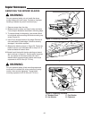
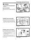
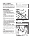
Figure 26. Trailing Arms
A. Spacers C. Nut
B. Rear Mower Rollers D. Rear Trailing Arms
MOWER ADJUSTMENTS
If the cut is uneven, the mower may need leveling.
Unequal or improper tire pressure may also cause an
uneven cut. Make sure tire pressure is correct as speci-
fied in Checking Tire Pressure. To achieve proper mower
levelling, perform Side-To-Side Leveling, Front-To-Back
Leveling and Transport Height Adjustment procedures, in
order, as follows.
Side-To-Side Leveling
1. With the mower installed, place the rider on a
smooth, level surface such as a concrete floor. Turn
the front wheels straight forward.
2. Check for bent blades and replace if necessary.
3. Loosen nut (C, Figure 26) so trailing arms are loose.
Mower must be resting on rollers with no weight on
trailing arms.
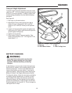
4. Use the Dial-A-Cut
TM
Control (E, Figure 27) and
place mower in mid-cut position by aligning front
edge of mower lift lever (A) with number 2 or 3 on
quadrant scale. Make sure mower lift lever is in down
position.
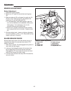
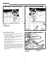
5. Make sure rear rollers (C, Figure 28) are on the
ground. If not, refer to Transport Height Adjustment.
NOTE: If rollers do not rest on the ground and it is
necessary to perform transport height adjustment, it
is necessary to perform transport height adjustment
again after all leveling procedures are completed.
6. Position blade(s) side-to-side and measure distance
from outside tip of blade(s) to ground. Measurement
should be equal (within 1/8”).
7. See Figure 28. On left side of mower, make sure
eccentric nut is in correct position as shown. Loosen
outside nut (A) and rotate eccentric nut (B) so that flat
side with hole closest to it is towards the rear. Tighten
outside nut (A) while holding eccentric nut (B).
8. On right side of mower, loosen outside nut (A). Turn
eccentric nut (B) counterclockwise to raise side of
mower, or clockwise to lower right hand side of
mower.
NOTE: Do not turn eccentric nut more than 1/4 turn in
either direction. When adjusted beyond 1/4 turn, nut will
move mower in opposite direction than when starting
adjustment.
9. When adjustment is correct, hold eccentric nut (B)
and tighten nut (A) to 30 ft-lbs. Check measurement
on both sides of mower.
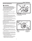
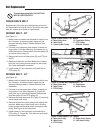
WARNING
Before checking mower, shut off PTO and engine.
Allow all moving parts to stop. Remove ignition key,
then disconnect the spark plug wire and fasten it
away from the spark plug.
WARNING
Mower blades are sharp. Turn the mower drive belt
to rotate blades into position or wear protective
gloves to protect against injury.
Figure 27. Controls
A. Mower Lift Lever D. Clutch/Brake Pedal
B. Parking Brake Knob E. Dial-A-Cut
TM
Control
C. Ground Speed Control Lever
+
-
B
A
E
C
D