


26
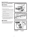
Adjustments
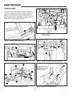
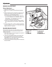
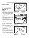
BRAKE ADJUSTMENT
Brake Adjustment
1. Release the parking brake.
2. Brake arm (C, Figure 25) should be touching stop
(B).
3. Remove cotter pin (D) and loosen the castle nut (A).
Place a 0.015” feeler gauge (E) gap between the
brake disc (F) and the brake puck (G).
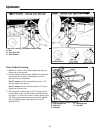
a. To decrease gap, insert feeler gauge in gap and
turn nut (A) clockwise until resistance is felt on the
feeler gauge. To increase gap, turn nut (A)
counter-clockwise and recheck gap.
b. Back off nut (counter-clockwise) until the nearest
slot is aligned with hole in threads. Replace cotter
pin.
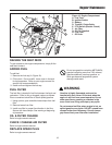
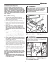
3. Set the parking brake. Loosen or tighten adjustment
nut (H) to achieve a 1-5/8” -1-3/4” compressed spring
length as shown in Figure 24.
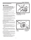
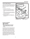
BLADE BRAKE CHECK
Mower blades and mower drive belt should come to a
complete stop within five seconds after electric PTO
switch is turned off.
1. With rider in neutral, PTO disengaged and operator in
seat, start the rider engine.
2. Look over the left-hand footrest at the mower drive
belt. Engage the PTO and wait several seconds.
Disengage the PTO and check the amount of time it
takes for the mower drive belt to stop.
3. If mower drive belt does not stop within five seconds,
see your dealer.
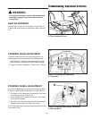
Figure 25. Brake Adjustment
A. Castle Nut E. Feeler Gauge
B. Stop F. Brake Disc
C. Brake Arm G. Brake Puck
D. Cotter Pin H. Adjustment Nut
E
B
F
A
C
D
H
1-5/8” - 1-3/4”
G