


14
Operating the Rider
SELECTING GROUND
& ENGINE SPEED
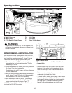
Ground speed is selected by depressing the clutch/brake
pedal (D, Figure 4) and moving the control lever (C,
Figure 4) to the appropriate speed selection. If the ter-
rain is rough, hilly or sloping, use first or second gear. If
the grass is wet or over 3” (76mm) high, use full engine
speed (with slow ground speed) so the mower will have
enough power to cut the grass.
1. If you are ready to mow, lower the mower from the
transport position using lever (A, Figure 4) and set
the mowing height using the Dial-A-Cut
TM
Control (E,
Figure 4).
2. Set the engine throttle for full speed.
3. Use the PTO switch to engage the PTO.
4. Release the parking brake by depressing the
clutch/brake pedal and pushing knob (B, Figure 4)
down.
5. Move the ground speed control lever (C, Figure 4) to
the desired direction and speed of travel to set the
rider in motion.
6. Adjust engine throttle to the desired speed. Full throt-
tle is recommended for mowing.
STOPPING THE RIDER
1. Move the ground speed control lever (C, Figure 4)
into the NEUTRAL position to make a gradual stop.
To make a more rapid stop, depress the /brake pedal
(D, Figure 4).
NOTE: The ground speed control lever will return to
neutral from forward automatically when the
clutch/brake pedal is depressed.
2. Engage the parking brake by fully depressing brake
pedal and pulling up on parking brake knob (B,
Figure 4).
3. Use the PTO switch (G, Figure 1) to disengage the
PTO.
4. Set the engine throttle (M, Figure 1) to 1/2 throttle
setting and allow the engine to idle for 20 seconds.
Stopping a hot engine too fast may cause engine
damage.
5. Turn key (C, Figure 1) to OFF and remove it.
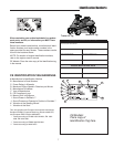
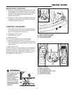
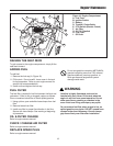
Figure 4. Controls
A. Mower Lift Lever D. Clutch/Brake Pedal
B. Parking Brake Knob E. Dial-A-Cut
TM
Control
C. Ground Speed Control Lever
OPERATING THE MOWER
1. When traveling to or from the work site, fully raise the
mower using the mower lift lever (A, Figure 4). At the
work site, lower mower using the lift lever.
2. Use the Dial-A-Cut
TM
control (E, Figure 4) to adjust
the height of the mower. Pull back slightly on mower
lift lever (A, Figure 4) to relieve pressure and turn
clockwise to raise mower cutting height, or counter-
clockwise to lower cutting height.
3. Engage the parking brake. Make sure the PTO
switch is disengaged.
4. Start the engine (see STARTING THE ENGINE).
5. Fully lower the mower using the attachment lift lever.
6. Set the throttle to FULL.
7. Engage the PTO (Mower Deck).
8. Begin mowing. See Section LC for tips on mowing
patterns, lawn care, and troubleshooting information.
9. When finished, shut off the PTO and raise the mower
using the attachment lift control lever.
10. Stop the engine (see STOPPING THE RIDER).
NOTE: Cutting height scale is located on the quadrant at
base of lift lever. Scale is numbered 1 thru 4, with 4 rep-
resenting the highest cutting height.
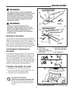
WARNING
Make certain
direction of travel
is clear of objects,
people and
animals.
Always look
DOWN AND
BEHIND before
backing!
WARNING
Make certain the area
of operation, and
especially the
direction of travel is
clear of objects,
people and animals.
Always look DOWN
AND BEHIND before
backing!
+
-
B
A
E
C
D