


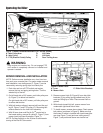
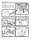

MOWER REMOVAL AND INSTALLATION
NOTE: Perform mower installation on a hard, level sur-
face such as a concrete floor. For easier mower removal
and installation, rear trailing arms (F, Figure 7) can be
removed by removing spring clips and clevis pins.
1. Park rider and turn off PTO switch and engine,
remove the key and apply parking brake. Turn the
wheels fully to the left.
2. On left-hand side of 34” mower, push idler pulley arm
(A, Figure 7) to relieve belt tension.
On right-hand side of 30” mower, pull idler pulley arm
to relieve belt tension.
3. With belt tension relieved, remove belt from idler pul-
ley (B, Figure 7) and PTO pulley (C). Removing belt
relieves tension on the front hitch assembly.
4. With lift lever down and Dial-A-Cut
TM
control set to
the lowest setting, remove lift cable (D, Figure 7) from
mower hook (see inset illustration, Figure 7).
NOTE: Pull back slightly on the lift lever to allow easier
turning of the Dial-A-Cut
TM
control.
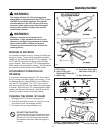
Figure 7. Mower Removal/Installation (34” mower shown)
A. Idler Pulley Arm D. Lift Cable
B. Idler Pulley E. Lift Hook
C. PTO (Electric Clutch) Pulley F. Rear Trailing Arms
*2396
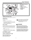
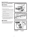
Figure 8. Mower Hitch
A. Lever C. Rider Hitch Brackets
B. Mower Hitch
*2390
5. Remove mower hitch (B, Figure 8) from rider hitch
brackets (C) by pulling spring-loaded lever (A) for-
ward and lifting up on hitch. Place mower hitch on
ground.
6. With wheels turned fully left, remove mower from
underneath right-hand side of rider.
7. To install mower, reverse above steps. Check mower
belt pattern (as shown in Figure 5). Make sure that
the mower lift cable is installed with hook toward the
rear (see Figure 7 inset) and rear trailing arms (F,
Figure 7) are positioned above rear torsion bar.
16
Operating the Rider
WARNING
Stop engine and remove key. Do not engage PTO
until mower is completely removed or installed and
operator is seated.