


25
Troubleshooting, Adjustment & Service
WARNING
To avoid serious injury, perform adjustments only
with engine stopped, key removed and rider on
level ground.
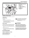
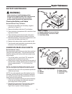
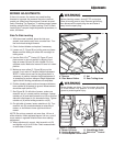
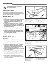
Figure 23. Steering Gear Adjustment
A. Capscrews
*2401
Capscrews
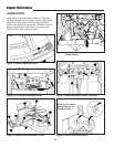
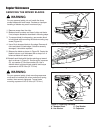
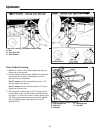
Figure 24. Steering Wheel Height Adjustment
A. Steering Shaft
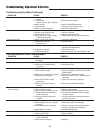
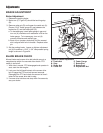
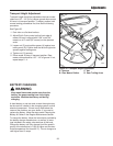
SEAT ADJUSTMENT
Use the lever on the front of the seat (A, Figure 22) on
to adjust the seat forward or rearward for best rider com-
fort.
A
STEERING GEAR ADJUSTMENT
If there is excessive slack in the steering system, the
steering gear can be re-indexed to the steering shaft.
1. See Figure 23. Loosen the two capscrews (A) and
push bracket so that gear teeth are closely meshed.
2. Tighten nuts after adjustment. Torque to 35 - 40ft-lbs.
STEERING WHEEL ADJUSTMENT
Your unit is equipped with a dual position steering shaft
to allow for steering wheel adjustment for rider comfort.
1. Pull down on the rubber boot to expose the two holes
in the steering shaft (A, Figure 24).
2. Use a suitable drift to remove the roll pin at the base
of the steering wheel.
3. Align the hole in the steering wheel with the appropri-
ate steering shaft hole and install the roll pin.
NOTE: Steering wheel is factory installed with the roll pin
in the bottom hole.
Figure 22. Seat Adjustment
A. Seat Adjustment Lever
A