


Initial Hitch & Tube Installation
12
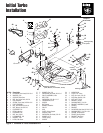
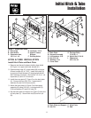
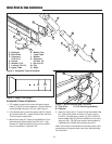
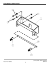
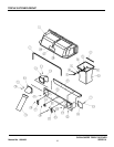
Figure 4. Assemble Tubes & Deflector
A
B
G
D
H
K
F
M
L
E
C
A. Deflector
B. Back Plate
C. Capscrew,
5/16-18 x 1
D. Socket
E. Washer, 5/16
F. Locknut, 5/16-18
G. Upper Tube
H. Middle Tube
I. Lower Tube
J. Washer
K. Capscrew,
#10-32 x 1/2
L. Nut, #10-32
M. Clip
N. Holes
A
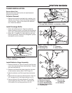
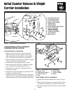
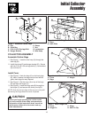
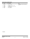
Figure 6. Mount Deflector and Tube Pivot
A. Tube Pivot C. 5/16” Mounting Hardware
B. Deflector
B
C
Assemble Tubes & Deflector
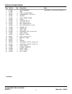
1. 50” models covered by this manual require upper
tube (G, Figure 5) to be shortened. Shorten tube by
cutting through along line “B” line. See Figure 5.
2. If not already done, insert the upper tube (G, Figure
4) into the socket (D). Insert the tube from the front.
This will require some effort.
3. Mount the socket (D, Figure 4) and deflector (A) to
the back plate (B) using the four 5/16-18 x 1 cap-
screws (C), eight flat washers (E), and four nylock
nuts (L) as shown in Figures 4 & 6.
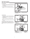
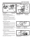
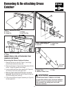
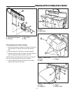
4. Insert the lower tube (I, Figure 4) into the middle tube
(H). Secure the tubes as shown in Figure 4 using
#10-32 x 1/2 capscrews, washer (J) and #10-32 nut.
Insert middle tube (H) (Secure the elbow to the turbo
using clip (M). Clip (M) may need to be relocated to
a different set of holes (N) to ensure secure fit.
Note: Use correct hole locations to maintain proper tube
connections and prevent lower tube from disconnecting
from the turbo.
I
J
A B
E
Figure 5. Upper Tube Length
N