


Initiai Hitch & Tube
Installation
11
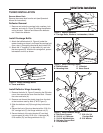
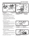
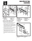
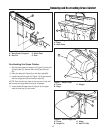
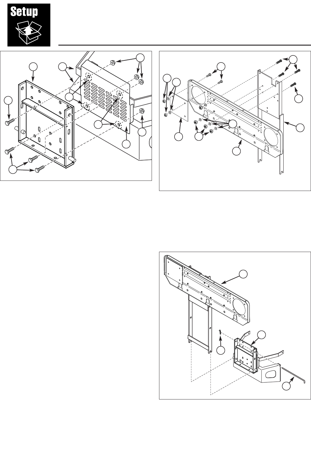
Figure 1. Install Hitch Plate
A. Hitch Plate D. Locknuts, 1/2-13
B. Heat Shield E. Upper & Lower
C. Capscrews Hex, Bumper
1/2-13 x 1-1/4 F. Exisitng Holes
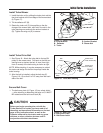
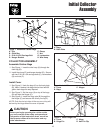
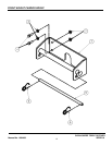
Figure 3. Install Back Plate
A. Back Plate and Support C. Hitch Plate
B. Hair Pin D. Rod
B
A
D
C
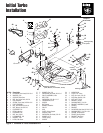
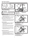
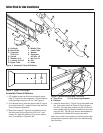
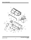
Figure 2. Install Hitch Assembly
A. Back Plate G. Carriage Bolts,
B. Support Assembly 5/16-18 x 1
C. Lockwashers, 5/16 H. Nylock Nut, 5/16-18
D. Nut, 5/16-18 I. Capscrews,
E. Washers, 5/16 5/16-18 x 3/4
F. Cover Plate
E
A
C
B
A
D
D
C
HITCH & TUBE INSTALLATION
Install Hitch Plate and Back Plate
1. Remove and discard hardware holding heat shield
(B, Figure 1) to upper and lower bumper (E).
2. Open exisitng holes (F) in heat shield (B) and upper
& lower bumper (E) to 17/32”. Install hitch plate (A)
to upper and lower bumper (E) keeping heat shield
(B) in between as shown. Secure with 1/3-13 x 1-1/4
capscrews (C) and 1/2-13 locknuts.
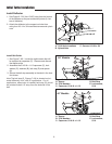
2. Install the cover plate (F, Figure 2) on the back plate
(A). Secure with four 5/16-18 x 1 capscrews (I),
washers (E) and 5/16-18 locknuts (H).
3. Attach the back plate (A, Figure 2) to the support
assembly (B) using 5/16-18 x 1 carriage bolts (G),
5/16 lockwashers (C) and 5/16 nuts (D).
4. Set the back plate and support (A, Figure 3) onto pins
of hitch plate (C). Secure with rod (D) and hair pin
(B).
G
G
B
E
C
D
H
I
F
F
F