


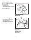

6
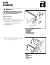
Latch Installation
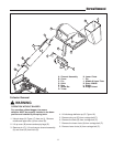
Figure 6. Install Latch & Hinge to Cover Assembly
A. Cover Assembly
B. Latch
C. Locknuts, ESNA, #10-24
D. Screws, #10-24 x 5/8
E. Hinge
F. Locknuts, 1/4-20
G. Screw, Slotted, 1/4-20 x 1/2
A
D
C
B
F
E
F
G
INSTALL LATCH AND HINGE TO COVER ASSEMBLY
1. Install the latch (B, Figure 6) to the cover assembly
(A) securing with #10-24 x 5/8 screws (D) and #10-24
locknuts (C) as shown.
2. Install the hinge (E) to cover assembly securing with
1/4-20 x 1/2 screws (G) and 1/4-20 locknuts (F).
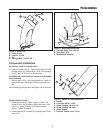
Figure 7. Install Channel Assembly
A. Channel Assembly
B. Hitch
C. Pin
C
B
A
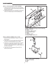
INSTALL CHANNEL ASSEMBLY AND “U”-TUBE
1. Slide the channel assembly (A, Figure 7) into hitch
(B) as shown.
2. Install the pin (C) into the right side of hitch (B) and
turn pin (C) counterclockwise to lock in place.
3. Install the “L” channel (E, Figure 8) and “U” tube (A)
to channel assembly (B) as shown. Secure with
5/16-18 x 1-3/4 carriage bolts (C), saddle clamps (F),
and 5/16-18 nuts (D).
4. Install 5/16-18 x 3/4 capscrew (G) and 5/16-18
locknut (D) as shown.