


Service
27
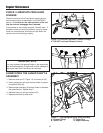
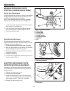
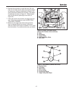
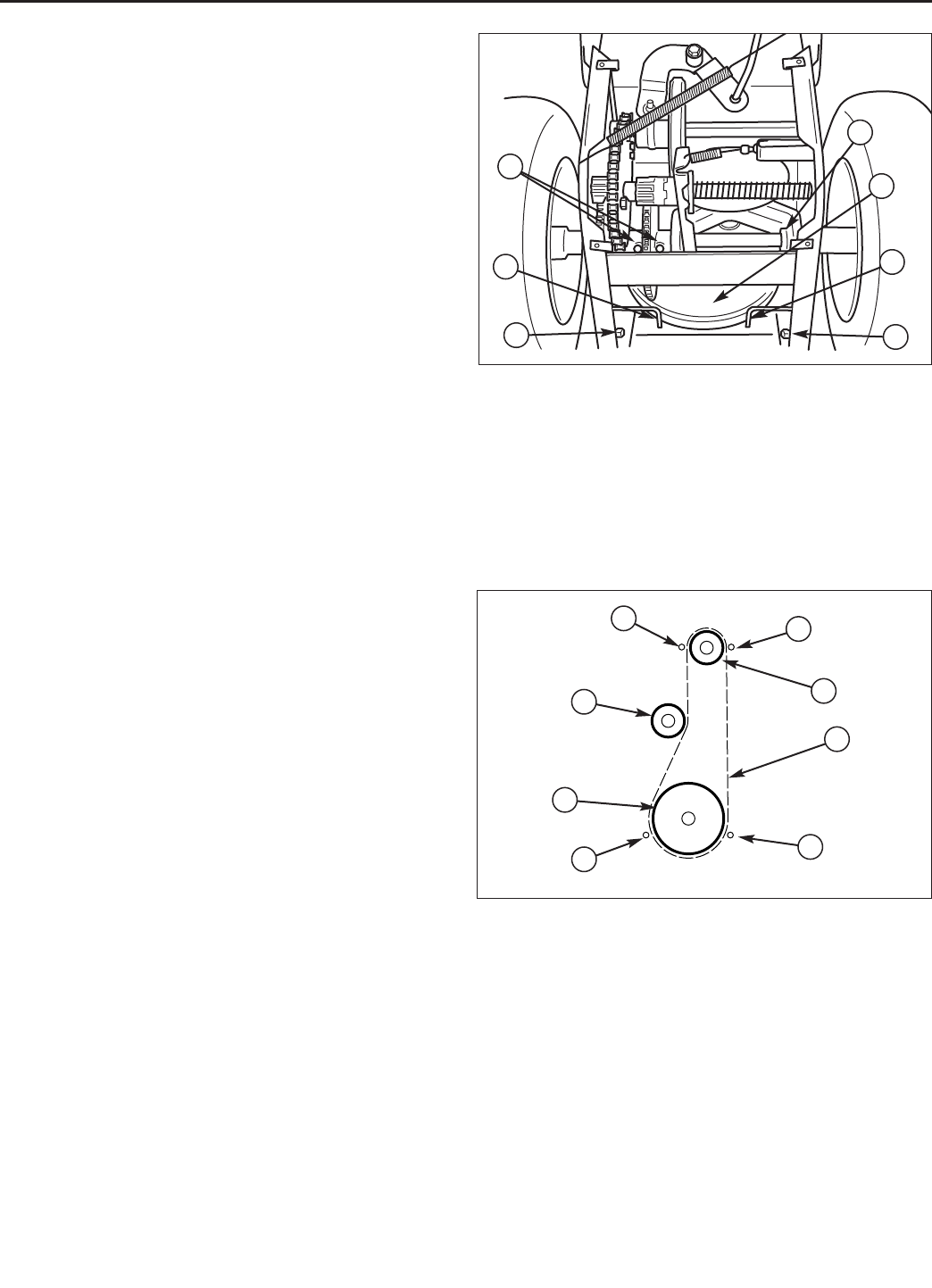
Figure 31. Belt Pattern (viewed from front)
A. Engine Pulley
B. Drive Belt
C. Idler Pulley
D. Driven Pulley
E. Engine Belt Stops
F. Auger Pulley Belt Stops
B
C
A
E
E
F
F
D
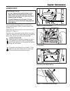
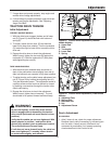
6. Reverse the procedure to install the belts. Be sure
there are no twists and the belts are properly seated
in the grooves. Adjust the belt stops so there is 1/8”
(3mm) clearance between belt and stop. The pattern
for both belts is shown in Figure 31. Slide the right
axle left fully before tightening the set collar (E,
Figure 30).
7. Check the traction drive tension and auger drive ten-
sion. Follow the procedures under AUGER/TRAC-
TION DRIVE TENSION.
8. Make sure the auger stops when the auger drive
lever is released. Make sure traction drive stops
when the traction drive lever is released. If not, check
the drive tension. If a problem exists, see your dealer.
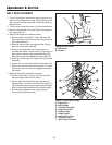
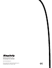
Figure 30. Auger Pulley Belt Stops
(shown with bottom cover removed)
A. Nuts
B. Belt Stops
C. Auger Pulley
D. Gear Assembly. Bolts
E. Set Collar
A
B
C
E
A
B
D