


Adjustments
24
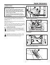
MANUAL DISCHARGE CHUTE
CONTROL LINKAGE ADJUSTMENT
Pinion Gear Adjustment
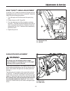
If the discharge chute is difficult to operate, first lubricate
the pinion gear (A, Figure 23) and ring gear (F). If it is
still difficult to operate, adjust as follows:
NOTE: If the discharge chute will not stay in position,
adjust the pinion gear (A) closer to the ring gear (F).
1. Loosen the nut (G, Figure 23) which holds the pinion
gear bracket in the slotted hole.
2. If the pinion gear is too tight against the ring gear,
move it away slightly and then retighten the nut.
3. Check the operation again
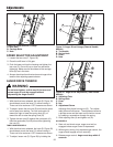
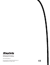
Figure 23. Discharge Control
A. Pinion Gear
B. Control Rod
C. Carriage Bolt
D. Slotted Bracket
E. U-shaped Bracket
F. Ring Gear
G. Nut
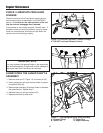
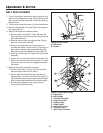
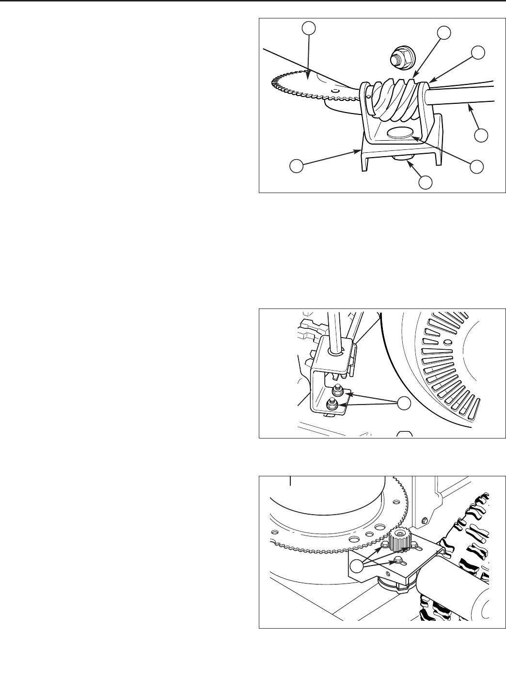
Figure 24. Gear Bracket Adjustment
A. Mounting Hardware
Gear Bracket Adjustment
If the discharge chute becomes difficult to rotate or
begins to operate erratically, the chute direction control
rod gears may require adjustment:
1. Loosen the gear bracket mounting nuts (Figure 24).
2. Slide the gear bracket into the position that provides
the best engagement between the gears.
3. Tighten the bracket mounting hardware, and check
for smooth operation.
4. Readjust if necessary.
5. Lubricate the chute direction control rod gears with a
medium weight (10W) oil
B
C
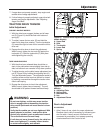
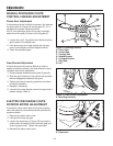
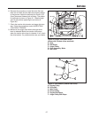
Figure 25. Chute Rotator Motor Adjustment
A. Capscrews
G
A
E
F
D
ELECTRIC DISCHARGE CHUTE
ROTATOR MOTOR ADJUSTMENT
If the electric chute rotator does not function properly,
check the electrical connections and then perform the
procedure below.
1. Remove the rotator motor cover.
2. Lubricate the chute ring gear.
3. Loosen the capscrews (A, Figure 25) securing the
rotator motor and adjust so that the motor gear and
chute ring gear mesh. Tighten the capscrews.
4. Reinstall the rotator motor cover.
A
A