


Adjustments
22
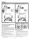
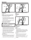
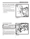
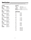
Figure 19. Auger Drive Linkage (Channel Handle
Models)
A. Turnbuckle
B. Spring Hook
C. Lever
D. Nuts
A
D
B
C
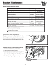
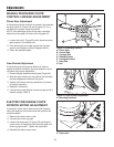
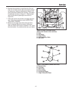
SPEED SELECTOR ADJUSTMENT
1. Loosen the two nuts (C, Figure 18).
2. Place the shift lever in 5th gear.
3. Push the lower rod into the housing and tighten the
two nuts (C). Do not lift up or down on rods while
tightening. Make sure the shoulders of the carriage
bolts (B) are in the slots.
4. Always check traction drive tension and auger drive
tension after adjusting speed selector.
AUGER DRIVE TENSION
CHANNEL HANDLE MODELS
1. With the drive lever released, the hook (B, Figure 19)
should barely touch the lever (C) without raising it.
There can be a maximum 1/32” clearance as shown.
2. To adjust, loosen the two nuts (D) and hold the lower
rod to keep from rotating. Turn the turnbuckle (A)
toward the right to lower the spring hook (B), or
toward the left to raise the spring hook (B).
3. Tighten the two nuts (D) against the turnbuckle (A).
Hold the turnbuckle (A) with pliers while tightening
the nuts (D).
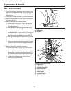
TUBE HANDLE MODELS
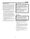
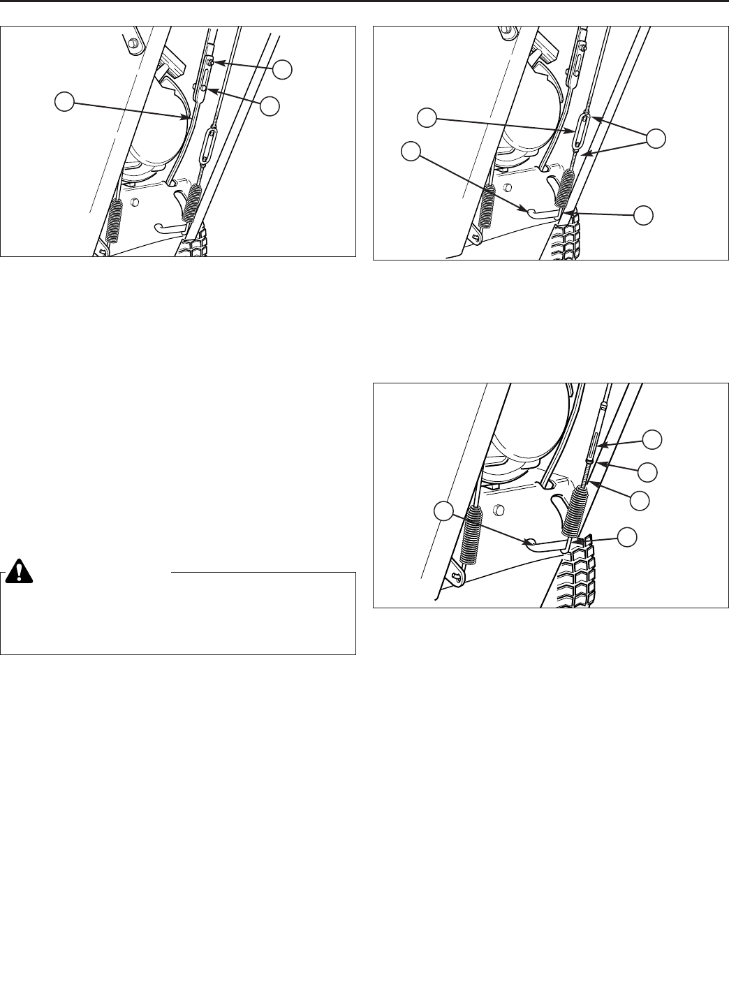
1. With the drive lever released, the hook (B, Figure 20)
should barely touch the lever (C) without raising it.
There can be a maximum 1/32” clearance as shown.
2. To adjust, loosen nut (D, Figure 20) by holding the
Figure 20. Auger Drive Adjustment (Tube Handle
Models)
A. Adjusting Flats
B. Spring Hook
C. Lever
D. Nut
E. Adjustment Screw
A
C
A
Figure 18. Speed Selector Linkage
A. Shift Rod
B. Carriage Bolts
C. Nuts
B
C
WARNING
Do not over-tighten, as this may lift the lever and
cause auger drive to be engaged without
depressing the Auger Control.
adjusting flats (A)and turning nut (D). Turn adjust-
ment flats and hold screw. The adjustment screw is
a phillips screw and the head can be held or turned
by inserting a screwdriver through the spring.
3. Hold adjusting flats (A) and tighten nut (D).
ALL MODELS
4. Start unit and check auger. auger must not be
engaged unless auger control is depressed.
5. With engine running, fully depress auger control, the
auger should engage and run normally.
6. Release auger control. Auger must stop within 5
seconds.
D
E
B