


Page 9
SERIES 28HE BOILER INSTALLATION AND OPERATION INSTRUCTIONS
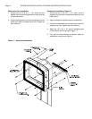
5. Insert the large port connector with its steel inner
ring into the upper port.
6. Insert the two round port connectors into the lower
ports.
NOTE: Apply the spray adhesive supplied with the
boiler to the port recess to hold the port connector
in place if necessary.
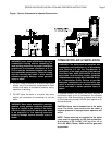
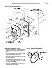
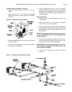
7. Select the correct intermediate section and carefully
move it into place against the back section, Figure
4.
CAUTION: Any steam uptake and heater sections
must be located as shown in Table 3. Failure to
comply with this caution may result in poor boiler
performance and prevent the jacket from fitting!
Only one intermediate section with an external leg
boss has been included. It should be located toward
the front of the boiler for optional low water cutoff
use. See Table 3.
NOTE: A putty knife or similar tool can be used to
hold the port connectors in place while the
intermediate section is positioned. It must be
removed before the sections make contact or the
port connector will be damaged resulting in a leak!
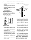
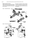
8. Insert the four draw rods through the casting
bosses. Thread nuts onto one end of the rods.
Place washers on the other end of the rods before
threading nuts onto them. Snug the nuts finger tight.
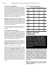
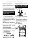
Use a spirit level to ensure that the first two sections
are plumb and properly aligned, Figure 6. Check the
rope to insure that it’s properly positioned. Once the
sections are plumb and the rope and port
connectors are properly positioned follow the torque
sequence shown in Table 4.
Figure 6 - Section Alignment
Table 4 - Section Torque Sequence
Step Rod Position Torque
ft lbs
Nm
1 Upper Right 25
34
2 Lower Left 25
34
3 Lower Right 25 34
4 Upper Left 10
14
5 Upper Right 50
68
6 Lower Left 50
68
7 Lower Right 50
68
8 Upper Right 75
102
9 Lower Left 75
102
10 Lower Right 75
102
11 Upper Left 30
42
12 Upper Right 125
169
13 Lower Left 125
169
14 Lower Right 125
169
15 Upper Right 125
169
16 Upper Left 40
54
NOTE: With these initial torques the sections may
not be metal to metal, which is acceptable. If any of
the ports leak during the hydrostatic test the torque
can be increased to 200 ft lbs,
271 Nm
on the upper
right rod. The torque on the lower left and right rods
can be increased to 150 ft lbs,
203 Nm
. Once the
sections are metal to metal additional torque will not
improve the seal.
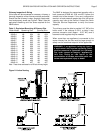
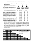
Boiler Section Location Numbered From Front To Back
Model 123456789101112131415161718
28HE-4 F T H B F Front Section
28HE-5 F H T H B T Intermediate Section w/ 5" Tapping & Boss
28HE-6 F T H T H B H Intermediate Section w/ Heater Opening
28HE-7 F T H P T H B P Intermediate Section, Plain
28HE-8 F T H P H T H B B Back Section
28HE-9 F T H P H P T H B
28HE-10 F H T H P H P T H B
28HE-11 F H T H P T P T H B
28HE-12 F H T H P T H P H T H B
28HE-13 F H T H P H T P P H T H B
28HE-14 F H T H P H T H P H P T H B
28HE-15 F H T H P H P T H P H P T H B
28HE-16 F H T H P H P H T H P H P T H B
28HE-17 F H T H P H P H T H P H P H T H B
28HE-18 F H T H P H P H P T H P H P H T H B
Table 3 - Section Locations