


Page 15
SERIES 28HE BOILER INSTALLATION AND OPERATION INSTRUCTIONS
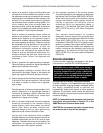
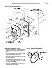
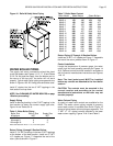
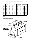
Figure 16 - Relief & Safely Valve Piping
WATER BOILER PIPING
The supply and return connections should be sized
to suit the system, see Figures 14, 15, 17, 18 and Tables
5 & 6. Do not pipe the supply from the bottom port or
the return to the top port, the boiler will not work
properly. Typical water boiler piping arrangements are
shown in Figures 19 & 20. Swing joints should be used.
Install 3" nipples into the two 3" NPT tappings in the
front section and cap them.
NOTE: See CLEANING OF WATER BOILERS on page
18 before proceeding!
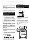
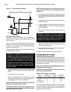
Supply Piping
Install a reducing bushing in the 6" NPT tapping in the
front section to obtain the correct supply pipe size,
Figure 14 and Tables 5 & 6.
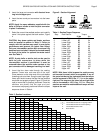
Table 6 - Water Boiler Piping
Boiler Size Return Size Supply Size
# Sections NPT NPT
4 & 5 3 3
6 through 9 4 4
10 through 18 5 5
Note: Sizes based on 20°F, 11.1°C, ∆T for the system.
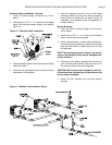
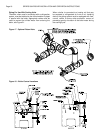
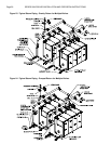
Return Piping 4 through 9 Section Boilers
Install 3" x 4" NPT bushings in the two 4" NPT tappings
at the bottom of the back section. Install two 3" NPT
x 6" nipples per Figure 17. Assemble the rest of the
return yoke as shown in Figure 17.
Table 7- Boiler Water Content
Boiler Model Water Boilers Steam Boilers
Gallons
Liters
Gallons
Liters
28HE-4 123
466
104
394
28HE-5 150
568
126
477
28HE-6 177
670
148
560
28HE-7 204
772
170
644
28HE-8 231
875
192
727
28HE-9 258
977
214
810
28HE-10 285
1079
236
893
28HE-11 312
1181
258
977
28HE-12 339
1283
280
1060
28HE-13 366
1386
302
1143
28HE-14 392
1484
324
1227
28HE-15 419
1586
346
1310
28HE-16 446
1689
368
1393
28HE-17 473
1791
399
1511
28HE-18 500
1893
412
1560
Return Piping 10 Through 18 Section Boilers
Install two 4" NPT x 6" nipples per Figure 17. Assemble
the rest of the return yoke as shown in Figure 17.
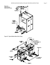
Control Installation
Locate the temperature & pressure gage, low water
cutoff, high limit and operating controls per Figures 14
& 18. Optional controls must be installed in accordance
with the control manufacturers instructions and Figures
14 & 18.
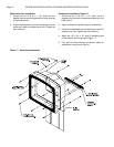
Note: The front jacket panel MUST be installed
before any controls are attached to the front boiler
section!
CAUTION: The controls must be mounted in the
correct location and according to the control
manufacturer’s instructions or the boiler may not
function properly!
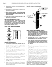
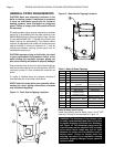
Water Column Piping
A variety of water level controls are available for the
28HE. The water column piping needed to properly
mount each control is available from Smith. Figure 18
shows a typical water column piping arrangement. The
1" NPT x 7 1/2" nipple is always installed in the lower
water column tapping, Figures 14 & 18 and Table 5.