


Page 10
SERIES 28HE BOILER INSTALLATION AND OPERATION INSTRUCTIONS
9. Assemble the rest of the sections following steps 3
through 8 above.
10. Hydrostatically test the boiler by following the
instructions on page 8.
11. While the boiler is being filled confirm that all
of the draw rods are properly torqued and that
there are no leaks.
12. If any leaks are found tighten the draw rods on that
section until the leak stops.
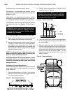
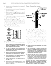
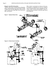
Heat Transfer Rod Installation, Figure 7
The high efficiency 28HE comes with design certified
heat transfer rod sets. Each tube of 15 heat transfer rods
will baffle one flue. In order to obtain the high efficiency
for which the boiler was designed, the heat transfer rods
must be properly installed, Figure 7.
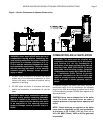
Figure 7 -Heat Transfer Rod Installation
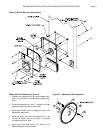
Cleanout Cover Installation
1. The cleanout covers come insulated from the
factory. Inspect the covers to ensure that the
insulation is not damaged or missing. If it is call the
Smith Customer Service Department.
2. Trim the 1/2" rope that’s sticking out around the
cleanout opening flush with the castings to insure
an air-tight seal, see Figure 5.
3. Install the cleanout cover bolts from the baffled side
of the cleanout cover and start the nuts, Figure 8.
4. Rotate the bolts so the cam heads fit between the
cleanout cover bosses on the castings.
5. Insert the cleanout cover and tighten the nuts to
15 ft lbs,
21 Nm
.
6. Apply a bead of high temperature silicone caulk
around the perimeter of the cleanout cover to
ensure an air tight seal.
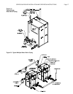
Figure 8 - Cleanout Cover Assembly
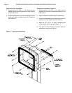
Burner Mounting Plate Installation, Figure 9
1. Apply two coats of the spray adhesive supplied with
the boiler to the rope groove on the plate. Allow time
for the first coat to dry then apply the second coat.
When the second coat is tacky lay the 3/8" rope into
the rope groove and press in place.
2. Screw the four 7/16-14 x 2 1/2" studs into the
tapped holes in the boiler front section, Figure 9.
3. Install the burner mounting plate insulation block in
the burner opening in the front section of the boiler.
The small observation port cutout must be on the
top, left side.
4. Position the front jacket panel frame over the four
studs, Figure 9.
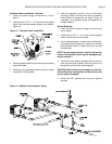
5. Align the four holes in the burner mounting plate
with the 7/16" studs and force the burner insulation
block inward until the studs extend far enough
through the burner mounting plate holes so the nuts
can be started. Lightly tighten the nuts.
6. Carefully insert the 1/4-20 x 5" machine screws
through the holes in the burner mounting plate and
insulation block, Figure 9. Reach through the inside
of the burner opening and install the stainless steel
fender washers and nuts and snug the nuts down.
CAUTION: The burner insulation block must be
supported from the inside to prevent it from tearing.
Don't force the bolts through the block or over
tighten the nuts or the block with be damaged!