


Page 14
SERIES 28HE BOILER INSTALLATION AND OPERATION INSTRUCTIONS
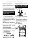
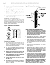
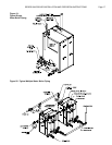
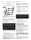
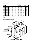
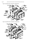
Figure 15 - Back Section Tapping Locations
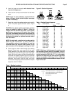
Table 5 - Water & Steam Tappings
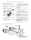
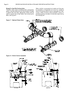
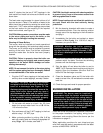
Relief & Safety Valve Piping
Install the pressure relief or safety valve in the 3" NPT
opening in the top of the back section, Figure 14.
WARNING: The discharge of the pressure relief
or safety valve must be piped close to the floor
to prevent scalding in the event of a discharge,
see Figure 16. The discharge piping must be
sized the same as the pressure relief or safety
valve outlet. Never install any type of valve
between the boiler and the pressure relief or
safety valve! Failure to comply with this
warning can result in an explosion causing
extensive property damage, severe personal
injury or death!
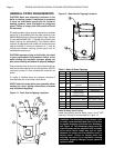
GENERAL PIPING REQUIREMENTS
CAUTION: Never use automotive antifreeze in the
boiler or heating system. If antifreeze is necessary
it must be formulated specifically for hydronic
heating systems, such as ethylene or propylene
glycol. Failure to comply with this caution will void
the warranty!
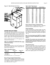
All heating system piping must be installed by a qualified
technician in accordance with the latest revision of the
ANSI/ASME Boiler and Pressure Vessel Code, Section
IV. Also ANSI/ASME CSD-1, Standard for Controls and
Safety Devices for Automatically Fired Boilers where
required. All applicable local codes and ordinances must
also be followed. A minimum clearance of 1" must be
maintained between heating system pipes and all
combustible construction.
CAUTION: Improper piping of this boiler can result
in poor performance and premature failure of the
boiler voiding the warranty! Improper piping can
also cause flooding and extensive property damage!
Ensure that the boiler is level from front to back and from
side to side. Use metal shims to level the boiler. NEVER
use wood, plastic or other combustible materials as
shims.
If a boiler is installed above any radiation elements it
must be fitted with a low water cutoff device.
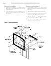
NOTE: Install the observation port assembly before
making any return piping connections as access
may be blocked by piping.
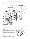
Figure 14 - Front Section Tapping Locations
Tapping Size Water Steam
1 1/8" Chamber Pressure Chamber Pressure
2 3/4" Probe LWCO
3 3/4" Temp./Pressure Gage
4 3/4" Operating Control - Top Water Glass
5
3/4"
Manuel Reset Manuel Reset High
High Limit Limit & Steam Gage
6 1" Air Removal Water Column - Top
7 6" Water Supply Skim Tapping
8 3/4"
Tankless Heater
Operating Control
9 1 1/2" Inspection Tapping - Top
10 1" Water Column - Bottom Water Column - Bottom
11 4" Boiler Drain Boiler Drain/Blowoff
12 4" Return Return
13 Relief Valve Safety Valve