


Page 18
SERIES 28HE BOILER INSTALLATION AND OPERATION INSTRUCTIONS
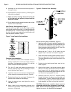
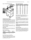
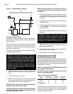
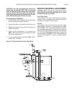
Figure 21 - Chilled Medium Diagram
Cleaning of Water Boilers
Normally the cleaning of water boilers is unnecessary
unless there is unusually heavy contamination of the
boiler or system.
The burner must be installed and made operational
along with the operating, limit and other safety controls.
The burner on oil boilers must be adjusted to prevent
sooting of the boiler flues.
Final burner adjustment should be made after the boiler
has been properly cleaned.
WARNING: The pressure relief valve must be
installed and piped to the floor to prevent
scalding in the event of a discharge, see Figure
16. The discharge piping must be sized the same
as the pressure relief valve outlet. Never install
any type of valve between the boiler and the
pressure relief valve! Failure to comply with this
warning can result in an explosion causing
extensive property damage, severe personal
injury or death!
1. Install ball valves on the two 3" NPT nipples in the
bottom of the front section and pipe to a suitable
drain.
2. Fill the boiler 3/4 full with water.
3. Make a cleaning solution by mixing 1 lb,
0.45 kg
each off caustic soda and trisodium phosphate for
every 50 ga,
189 L
of water, see Table 7.
NOTE: The water content of the heating system must
be added to the boiler water content.
CAUTION: Avoid skin contact with cleaning solution
to prevent injury! If eye or skin contact occurs flush
with large quantities of water.
NOTE
FOR HEATING: VALVES “H” OPEN, VALVES “C” CLOSED.
FOR COOLING: VALVES “H” CLOSED, VALVES “C” OPEN.
EXP. TANK
VENT
ROOM
UNIT
DRAIN
CHILLER
H
C
PUMP
RELIEF
VALVE
FILL
VALVE
DRAIN
H
BOILER
C
NOTE: Some locations do not allow this solution to
be used. Check with the local authority having
jurisdiction.
4. Mix the cleaning chemicals with water to create a
concentrated solution. Pour the cleaning solution
through one of the top tappings in the front section
and plug it.
5. Immediately fill the rest of the boiler and the heating
system with water.
6. Fire the boiler and maintain a water temperature
of 160°F to 200°F,
71
°
C to 93
°
C
it may be necessary
to cycle the boiler.
7. Run all of the system pumps during the cleaning
procedure.
WARNING: Monitor the boiler pressure
constantly during the cleaning procedure. Do
not allow the boiler pressure to exceed the
pressure listed on the pressure relief valve or a
discharge of hot water and steam will occur!
8. Shut the boiler off and allow the boiler to cool to
100°F,
38
°
C
. Open the 3" ball valves and drain the
boiler and heating system.
9. Remove the 3" ball valve and install 3" pipe caps in
the ends of the 3" NPT nipples.
10. Refill the boiler and heating system with water.
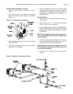
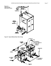
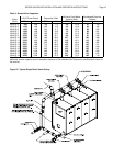
STEAM BOILER PIPING
Steam Boiler Piping Connections
Table 3 contains the steam riser location schedule. Riser,
equalizer and header pipe sizes are located in Table 8. A
typical single boiler piping arrangement is shown in Figure
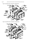
22. Figures 23 & 24 contain typical piping diagrams for
steam boilers in a battery.
NOTE: See CLEANING OF STEAM BOILERS before
connecting the return piping.
CAUTION: Improper placement of steam risers will
result in poor steam quality!
Table 8 - Steam Boiler Piping Sizes
Boiler Number of Header Equalizer
Model 5" NPT Risers Size, NPT Size, NPT
4 & 5 1 5" 2 1/2"
6 & 7 2 5" 2 1/2"
8 Through 10 2 6" 4"
11 Through 18 3 8" 4"
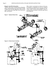
The steam piping should be pitched so the condensate
flows in the direction of steam travel. The return tappings
should be yoked to equalize the return flow, Figure 17.
Swing joints should be used.