12
TF22221
50-Hour Maintenance
CAUTION!
Make sure you do not pierce the fuel line
with the end of the hooked wire. The line
is delicate and can be damaged easily.
Every 10 to 15 hours of operation:
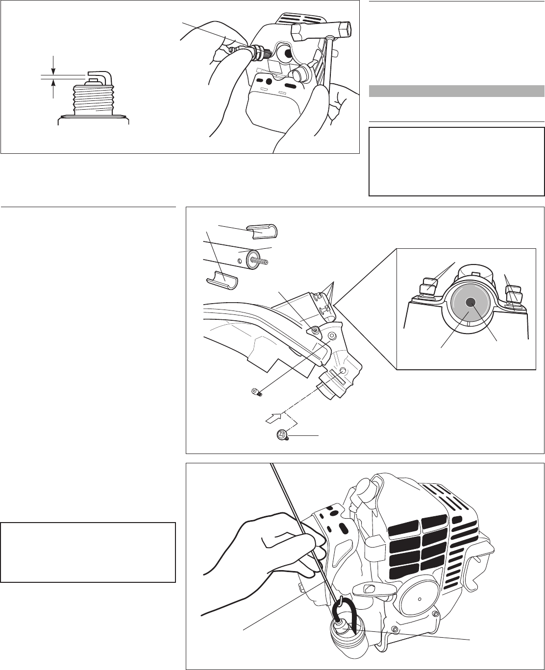
Remove and clean the spark plug. Adjust
the spark plug electrode gap to 0.024-
0.028 inch (0.6-0.7 mm). If the spark plug
must be replaced, use only an BPMR6A
or equivalent resistor type spark plug of
the correct heat range. See Figure 22.
■
CAUTION!
Before removing the spark plug, clean
the area around the plug to prevent
dirt and debris from getting into the
engine’s internal parts.
10/15-Hour Maintenance
NOTE:
The BPMR6A also meets the requirements
for electro-magnetic compliance (EMC).
Every 50 hours of operation (more
frequently in dusty or dirty conditions):
Gearcase Lubrication (T222 Only)
To perform this operation, first remove
the gearcase and debris shield from the
outer tube as follows. See Figure 23.
Remove the index bolt from the
gearcase.
Loosen the gearcase clamp screw.
Loosen the four socket head cap screws
that secure the cutting attachment
shield.
Slide the gearcase and cutting
attachment shield off the tube. (Do not
lose the two shims).
Remove the filler plug and press new
grease into the gearcase until old grease
is purged from the gearcase, which can
be seen in the outer tube cavity.
Clean up the excess grease and rein-
stall the cutting attachment shield, two
shims and the gearcase.
Remove and replace the lter
element.
1.
■
■
■
■
2.
3.
Use a hooked wire to extract the fuel
filter from inside the fuel tank. See
Figure 24.
Before reinstalling the new filter element,
inspect the condition of all the fuel system
components (fuel pick-up line, fuel return line,
tank vent line, tank vent, fuel cap and fuel
tank). If damage, splitting or deterioration is
noted, the unit should be removed from service
until it can be inspected or repaired by a
Shindaiwa-trained service technician.
1.
Shims
Clean the spark
plug and check
the gap at the
electrode.
0.024–0.028 inch
(0.6–0.7 mm)
Figure 22
Figure 24
Filter Element
Hooked
Wire
4 Socket Head Screws
Clamp Screw
Outer Tube
Figure 23
Index Bolt
Outer Tube
Cavity
4 Socket Head
Screws
Grease Plug
New Grease
Old Grease


