


35011
Installing a Blade T272X
Assembly and Adjustments
NOTE:
The T272X is shipped with Holder “A,” the
safety clip, Holder “B,” shaft bolt, and bolt
guard installed. The shaft bolt is a LEFT-
HAND THREAD AND IS REMOVED IN A
CLOCKWISE ROTATION!
NOTE:
When installing certain blades, it may be
necessary to temporarily remove the safety
clip.
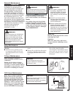
CAUTION!
Install the blade so its printed surface
is visible to the operator when the
brushcutter is in the normal
operating position.
WARNING!
The blade must fit flat against the
holder flange. The blade mounting
hole must be centered over the raised
boss on blade holder A.
35010
35013
35012
A
B
C
Shaft Bolt
Bolt Guard
Holder “B”
Holder
“A”
Gearcase
Shaft
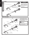
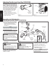
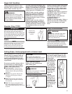
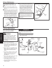
Slide the safety clip off-center
Center the safety clip
Slip the blade in place
Safety Clip
Figure 12
Hex
Wrench
ASSEMBLY
35015
35014
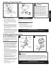
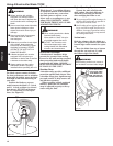
Install Holder
“B”
Blade
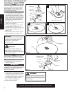
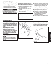
Tighten the assembly
Combination Spark
Plug/Screwdriver
Wrench
Hex Wrench
Bolt Guard
Holder “B”
Figure 14
Figure 13
6. Install Holder “B” on the gearcase
shaft. See Figure 13.
IMPORTANT!
The machined recess in Holder “B” must
completely surround the safety clip, and
both holders must be flat against the
surface of the blade.
Never operate the brushcutter without
the safety clip installed and both hold-
ers tightly secured and flat against the
blade surface!
WARNING!
The T272X should now be completely assembled to operate with a blade.
Blade not shown
for clarity
8
7. Lock holder "A" to the gearcase by in-
serting the long end of the hex wrench
through both holes as done in step 1
and tighten the shaft bolt securely with
the combination spark plug/screw
-
driver wrench. See Figure 14.
8. Remove the hex wrench.
1. With the gearcase output shaft facing
up, rotate the gearshaft and holder
"A" until the hole in holder "A" aligns
with the matching hole in the gearcase
flange, and then lock the holder to the
gearcase by inserting the long end of
the hex wrench through both holes.
See Figure 12.
2. Remove the shaft bolt, bolt guard and
holder B. See Figure 12.
3. Slide the safety clip off center on the
gearcase shaft. See Figure 12-A.
4. Slide the blade over the safety clip and
onto the flange on Holder “A.” See
Figure 12-B
5. Lock the blade on the shaft by center
-
ing the safety clip. See Figure 12-C.