


* Shindaiwa One meets or exceeds these specifications and is recommended for all Shindaiwa Products
** The EPA emission compliance referred to on the emission compliance label located on the engine, indicates the number of operating hours for
which the engine has been shown to meet Federal emission requirements. Category C = 50 hours (Moderate), B = 125 hours (Intermediate) and A =
300 hours (Extended).
DESCRIPTION
Engine Code ..................S272E Engine
Dry weight, T272
(less attachment) ............6.7kg/14.7 pounds
Dry weight, T272X
(less attachment) ............6.7kg/14.8 pounds
Type ..............................2-cycle, vertical cylinder, air
cooled
Bore x Stroke .................
34 mm x 30 mm/1.3 in. x 1.2 in.
Displacement .................27.2cc/1.7 cu. in.
Maximum Power Output .1.1 kw/1.4 hp
Operating rpm Range .....4,500-9,000 rpm (min
-1
)
Transmission Type .........Automatic centrifugal clutch
through bevel gears
Fuel/Oil Ratio ................50:1 with ISO-L-EGD or JASO
FC class 2-cycle mixing oil*
Specifications T272X/C272
Fuel Tank Capacity .........670ml/22.6 ounces
Carburetion ...................Walbro diaphragm-type
Ignition .........................Fully electronic, transistor
controlled
Spark Plug ....................Champion CJ8Y
Air Cleaner Type ............Non-reversible heavy-duty
filter element
Starting Method .............
Recoil
Stopping Method ............Slide switch, grounding type
Handle ..........................Loop handle (T272)
Loop handle with barrier bar
(T272X)
EPA Emission Compliance Period** Category A
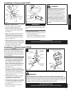
This unit comes fully assembled with
the exception of the cutting attach-
ment shield and cutting attachment.
Prior to Assembly
Before assembling, make sure you
have all the components required for
a complete unit and inspect unit and
components for any damage.
n Engine and shaft assembly
n Cutting attachment shield
n Cutting attachment
n Kit containing cutting attachment
shield bracket and hardware, this
owner's/opertor's manual and tool
kit for routine maintenance. Tool kits
vary by model and may include a hex
wrench set, spark plug/screwdriver
combination wrench and a spanner.
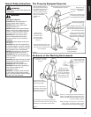
IMPORTANT!
The terms “left,” “left-hand,” and “LH”:
“right,” “right-hand,” and “RH”; “front” and
“rear” refer to directions as viewed by the
operator during normal operation of this
product.
5
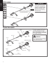
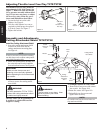
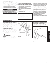
Handle T272/T272X
Assembly and Adjustments
The handle is attached to the outer tube
on the T272/T272X.
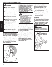
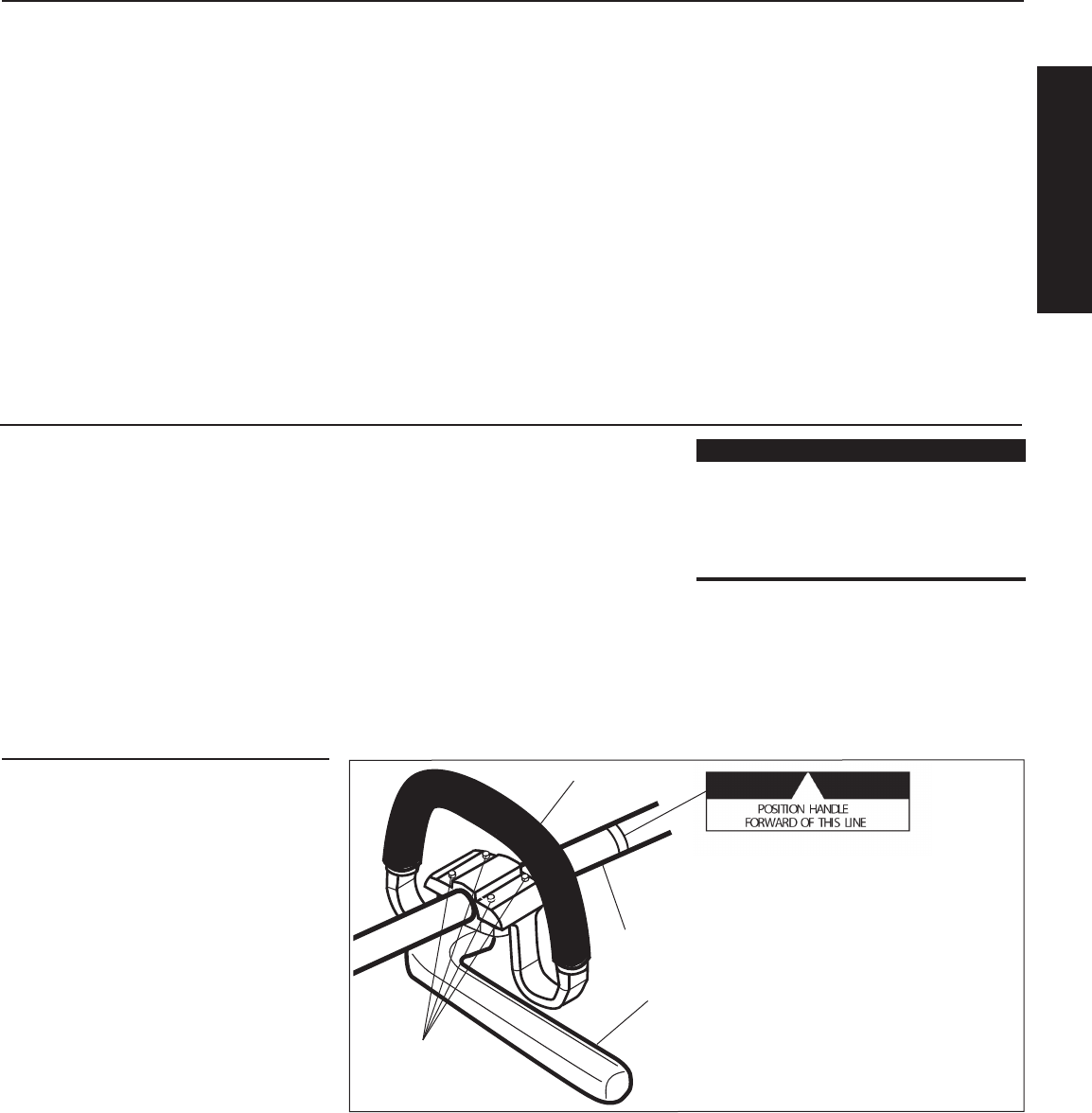
To Adjust the Handle.
1. Loosen the 4 socket-head capscrews on
the handle. See Figure 5.
2. Position the handle forward of the
Handle Positioning Label at the best
position for operator comfort (usually
about 10 inches ahead of the throttle
housing).
3. Secure the handle by alternately tight
-
ening the four socket-head cap screws
in a diagonal or “criss-cross” fashion.
Outer Tube
Handle
Handle Positioning Label
4 Socket-head Cap-
screws
Figure 5
Barrier
Bar
T272X Shown