


ASSEMBLY
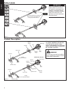
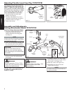
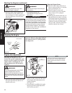
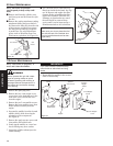
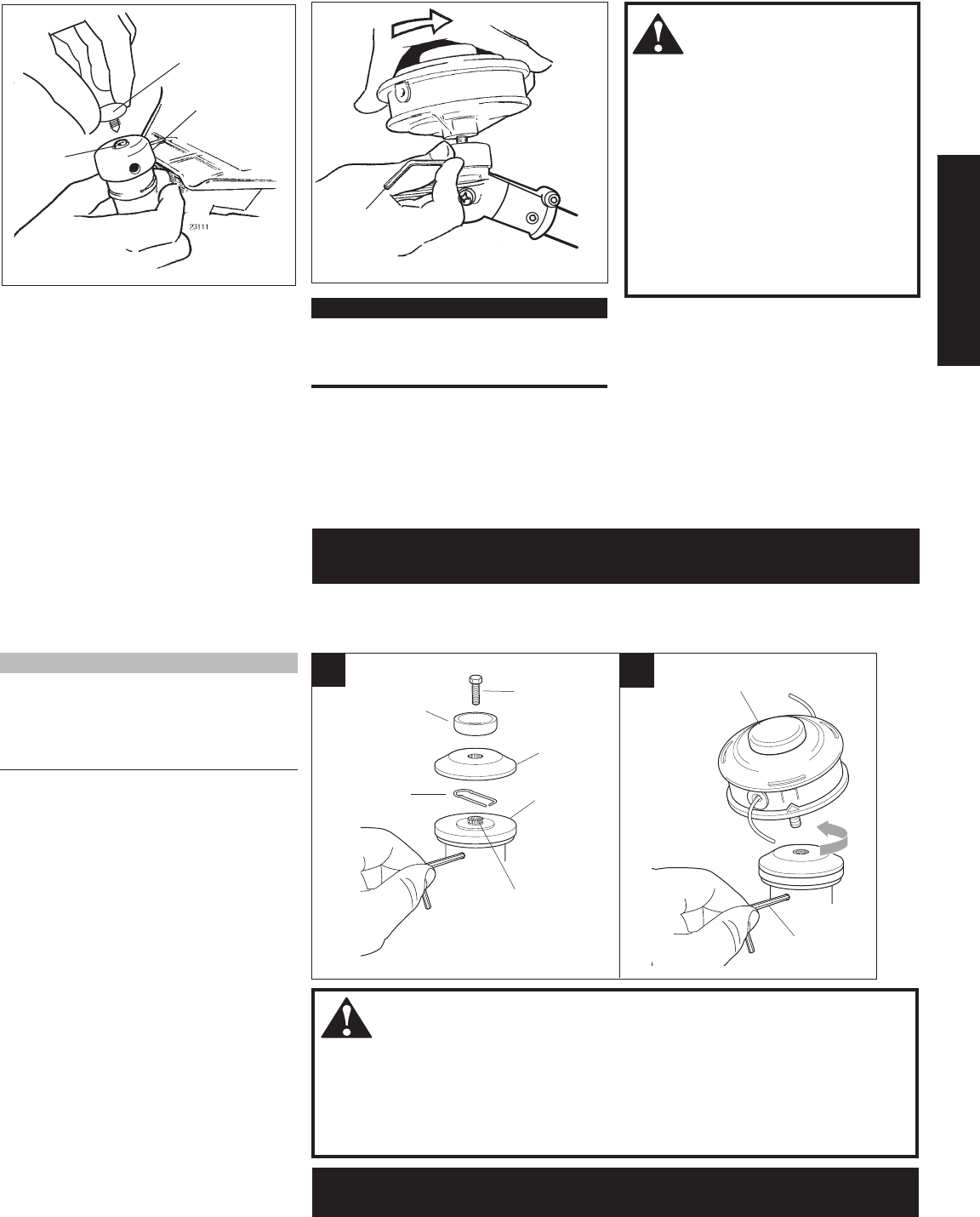
Installing a Trimmer Head T272X
35008
35007
A
Safety Clip
(not used)
Shaft Bolt
(not used)
Bolt Guard
(not used)
Gearcase
Shaft
Hex Wrench
B
Holder B
Holder A
Hand-tighten Trimmer Head (coun-
ter-clockwise to install)
Figure 11
NOTE:
The T272X is shipped with Holder A, the
blade retainer (safety clip), Holder B, shaft
bolt, and bolt guard installed. The shaft bolt
is a LEFT-HAND thread. Remove it by turn
-
ing CLOCKWISE!
1. With the gearcase output shaft facing
up, rotate the gearshaft and holder A
until the hole in holder A aligns with
the matching hole in the gearcase
flange, and then lock the holder to the
gearcase by inserting the long end of
the hex wrench through both holes.
See Figure 11-A.
2. Using the combination spark plug/
screwdriver wrench, remove the shaft
bolt, bolt guard, holder B and the safety
clip. (The bolt guard, shaft bolt and
safety clip are not used with a trimmer
head). See Figure 11-A.
3. Install Holder B on the gearcase shaft.
The splined hole on Holder B must
engage with the gearcase shaft.
4. Using the hex wrench to secure Holder
A , install and hand-tighten the trimmer
head (counter-clockwise to install).
See Figure 11-B.
5. Remove the hex wrench from the
gearcase and holder.
WARNING!
A standard grass trimmer unit with loop handle should NEVER be operated with
blade-type attachments. For blade use, the trimmer must be fitted with a bicycle-type
handlebar or barrier bar that is located in front of the operator to reduce the risk of the
operator coming in contact with the cutting attachment. (Per ANSI B175.3). When us
-
ing a blade, the unit must also be equipped with a harness or strap.
The T272X should now be
completely assembled and ready for use with a trimmer head.
7
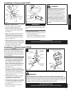
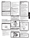
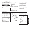
Install the Trimmer Head.
1. Turn the trimmer over so that the
gearcase output shaft faces UP.
2. Remove and discard the black plastic
protective cap from the output shaft.
See Figure 9.
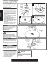
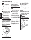
3. Rotate the holder until the hole in the
holder aligns with the notch on the
gearcase. Use the long end of the hex
wrench to lock the holder and output
shaft. See Figure 10.
4. While holding the hex wrench, thread
the trimmer head onto the output shaft,
turning counter-clockwise. Using hand
pressure only, tighten the trimmer
head firmly on the output shaft.
IMPORTANT!
The trimmer head has a left-hand thread.
For removal turn the trimmer head clock-
wise.
Figure 9
WARNING!
A standard grass trimmer with a loop
handle should NEVER be operated
with blade-type attachments. For
blade use the trimmer must be fitted
with a bicycle-type handlebar or a
barrier bar that is located in front of
the operator to reduce the risk of the
operator from coming in contact with
the cutting attachment (per ANSI
B175.3). When using a blade, the unit
must also be equipped with a harness
or strap.
Holder
Output
shaft
Retaining
Plug
Hex Wrench
5. Remove the hex wrench.
6. Adjust the trimmer line length to reach
no further than the line
cutter on the cutting attachment shield.
Trim to the correct length if necessary.
Installing a Trimmer Head T272
Figure 10
The T272 should now be
completely assembled and ready for use with a trimmer head.