


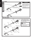
ASSEMBLY
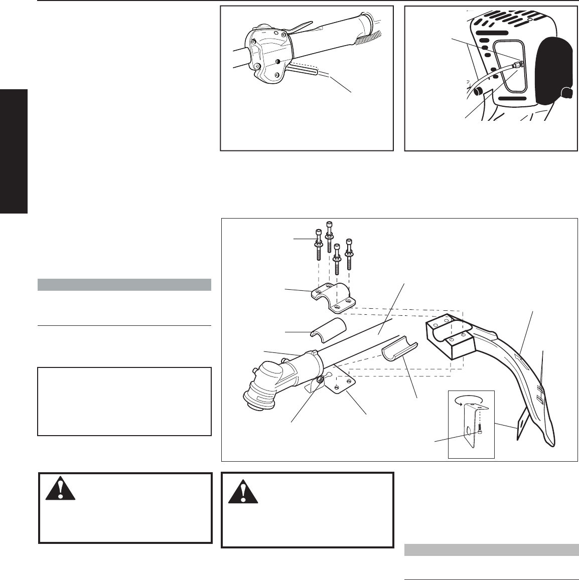
Cutting Attachment Shield T272/T272X
Assembly and Adjustments
Figure 8
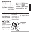
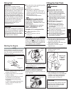
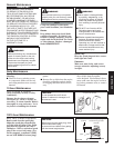
Install the Cutting Attachment Shield.
1. Insert the cutting attachment shield
between the outer tube and the
cutting attachment mounting plate.
See Figure 8.
NOTE:
It may be necessary to loosen the retaining
nut and clamp screw to adjust cutting attach
-
ment shield mounting plate.
WARNING!
NEVER operate the T272 or T272X
without the cutting attachment shield
installed and tightly secured!
1025
Cutting Attach-
ment Shield
Outer
Tube
Socket-
Head Cap
Screw
Bracket
Shim
Clamp Screw
Shim
Retaining
Nut
Cutting
Attachment
Mounting
Plate
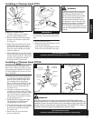
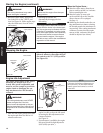
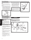
Line Cutter
Figure 8A
Hex
Screws
Nuts
WARNING!
The line cutter is very sharp. Wear
gloves to protect your hands
when handling.
To Change Position of Line Cutter.
1. Remove the 2 hex screws with a 4mm
hex wrench. See Figure 12A.
2. Rotate line cutter. See Figure 12A.
3. Reinstall the two hex screws and
tighten them securely.
The line cutter can be positioned in
2 positions to obtain different line
length for cutting.
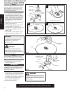
3. Tighten the four socket-head cap
screws to secure the cutting attach
-
ment shield.
NOTE:
Be careful to not lose the 2 nuts in the cut
-
ting attachment shield.
CAUTION!
Make sure the clamp screw and
retaining nut are securely tightened
before tightening the four socket head
cap screws.
6
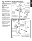
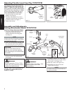
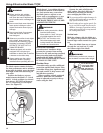
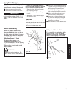
Adjusting Throttle Level Free Play T272/T272X
The throttle lever free play should be
approximately 9/32 inch (7mm). See
Figure 7. Make sure that the throttle
lever operates smoothly without bind-
ing. If it becomes necessary to adjust
the lever free play, follow the proce
-
dures and illustrations that follow.
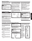
1. Loosen the lock nut on the cable
adjuster. See Figure 6.
2. Turn the cable adjuster in or out as
required to obtain proper free play of
9/32 inch (7mm). See Figure 7.
3. Tighten the locknut.
Figure 6
Cable
Adjuster
Locknut
9/32 inch
(7 mm)
Throttle Lever
Free Play
Figure 7
2. Fit the two shims and the bracket over
the outer tube and loosely install the
four socket-head screws. See Figure 8.