


MAINTENANCE
SE10-4A/SE15-4A 03/09 Maintenance Section 5-7
© 2009 Alamo Group Inc.
MAINTENANCE
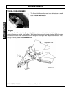
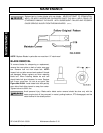
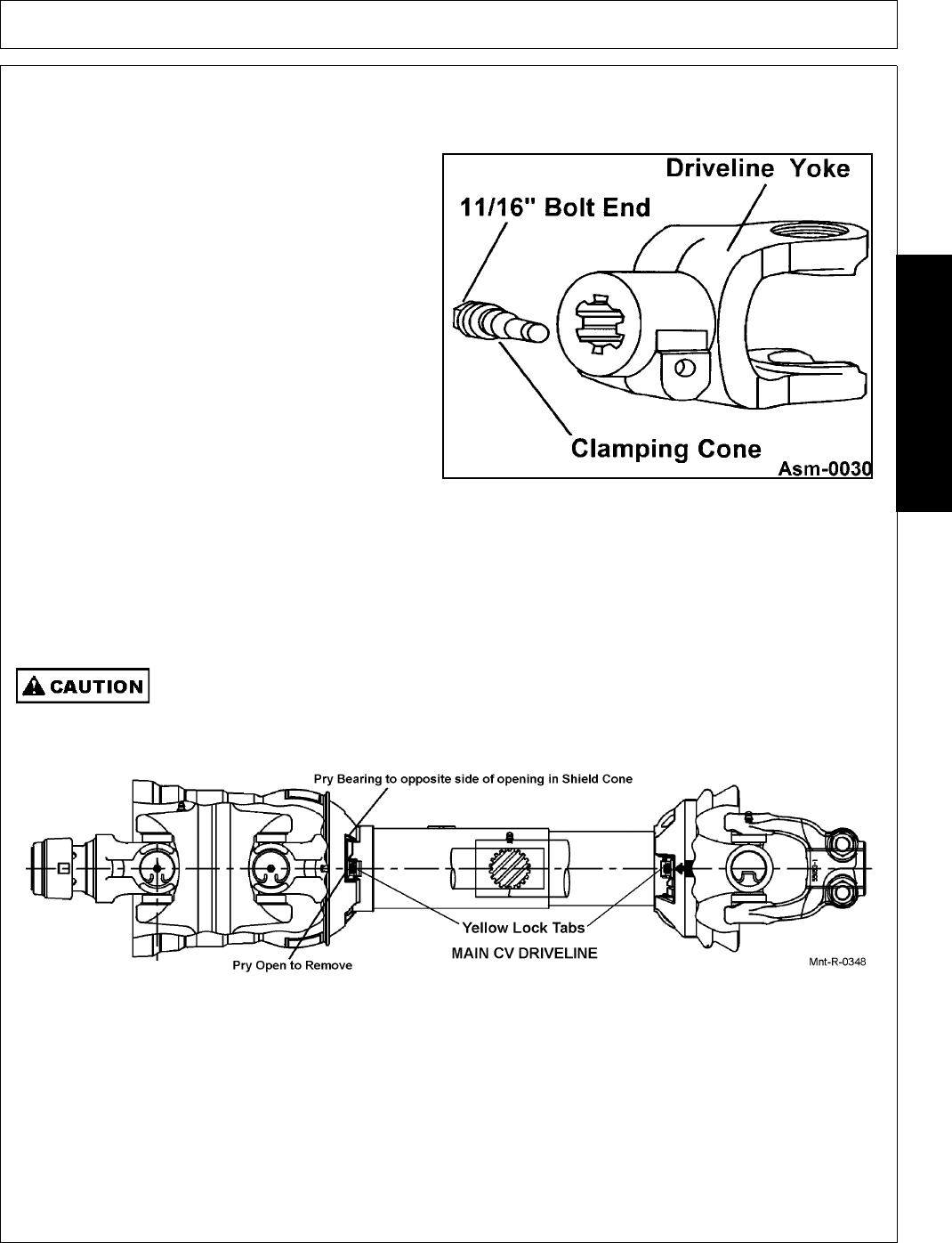
DRIVELINE CLAMP CONE YOKE
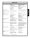
OPERATING INSTRUCTIONS
Loosen the yoke clamp cone with a 11/16” (17mm)
wrench and remove the cone from yoke. Slide yoke
onto the shaft and align hole for clamping cone with
annular groove of gearbox shaft. Reinstall cone and
tighten (75 lb-ft torque). Push and pull the driveline
to ensure it is securely attached to the shaft.
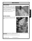
Regularly check the driveline yoke to ensure a tight
connection. To remove the yoke, remove the
connecting cone and pull yoke off the shaft. If the
cone cannot be easily removed by hand, drive it out
from the other side using a hammer and punch.
NOTE: The clamping cone is serviced only as a
complete assembly. Do not attempt to disassemble
the clamping cone.
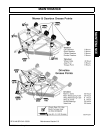
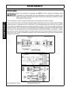
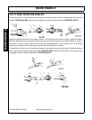
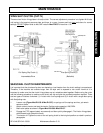
MAIN CV DRIVELINE SAFETY SHIELD
Protective Driveline Shields should e installed on Drivelines as shown in Figure Mnt-R-0218 below. The
protective Integral Shields are assembled onto nylon bearings and should turn freely. Push the locking lug of
the nylon bearing into the slot until it snaps into place.
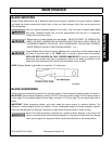
Do not overfill. If gearboxes are filled above Test Plug Level, pressure under working
conditions may cause Grease Seals to leak.
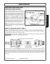
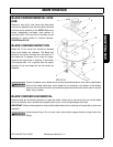
To remove shields or replace shield bearing pry open yellow lock tabs. Insert screwdriver between shield cone
and white bearing. Rotate tab of shield bearing over to yellow tab location. Pull on shield to remove. Bearing is
split and can be removed from yoke. To install shield reverse steps. Insert shield over bearing tube noting that
tabs must be where yellow tabs are located. Rotate shield tab until yellow tab can be pushed into place and it
locks there.