


8
ASSEMBLY/PRE-OPERATION
Your new tractor has been assembled at the factory with exception of those parts left
unassembled for shipping purposes. To ensure safe and proper operation of your tractor
all parts and hardware you assemble must be tightened securely. Use the correct tools
as necessary to ensure proper tightness.
TO REMOVE TRACTOR FROM
CARTON
UNPACK CARTON
• Remove all accessible loose parts and
parts cartons from carton .
•
Cut along dotted lines on all four pan-
els of carton. Remove end panels and
lay side panels flat.
• Remove mower and packing materials.
• Check for any additional loose parts or
cartons and remove.
BEFORE REMOVING TRACTOR
FROM SKID
NOTE: You may now roll your tractor off the
skid. Follow the ap pro pri ate instruction below
to remove the tractor from the skid.
WARNING: Before start ing, read, un-
der stand and fol low all in struc tions in the
Op er a tion section of this man u al. Be sure
tractor is in a well-ventilated area. Be sure
the area in front of tractor is clear of other
peo ple and objects.
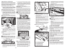
TO ROLL TRACTOR OFF SKID (See
Op er a tion section for location and
function of con trols)
1. Raise attachment lift lever to its high-
est po si tion.
2. Release parking brake by de press ing
brake ped al.
3. Place freewheel control in dis en gaged
po si tion to dis en gage trans mis sion (See
“TO TRANS PORT” in the Op er a tion sec-
tion of this manual).
4. Roll tractor forward off skid.
Continue with the instructions that follow.
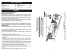
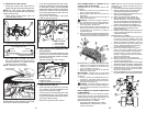
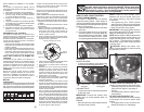
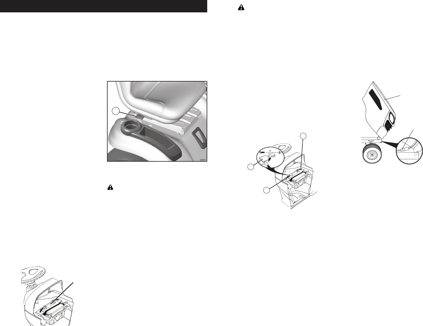
ADJUST SEAT
1. Sit in seat.
2. Lift up adjustment lever (A) and slide seat
until a comfortable position is reached
which allows you to press clutch/brake
pedal all the way down.
3. Release lever to lock seat in position.
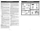
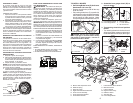
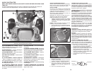
TO CHECK BATTERY
1. Lift hood to raised position.
NOTE: If this battery is put into service after
month and year indicated on label (label is
located between terminals) charge battery
for minimum of one hour at 6-10 amps. (See
"BATTERY" in Maintenance section of this
manual for charging instructions).
• For battery and battery cable installation
see "REPLACING BATTERY" in the
"Service and Adjustments" section in
this manual.
Label
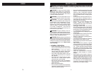
TOOLS REQUIRED FOR ASSEMBLY
A socket wrench set will make assembly
easier. Stan dard wrench sizes are listed.
(2) 7/16" wrenches Utility knife
(1) 1/2" wrench Tire pressure gauge
(1) 3/4" wrench Pliers
(1) 3/4" socket w/drive ratchet
(1) 9/16" wrench Flashlight
When right or left hand is mentioned in this
man ual, it means when you are in the operating
po si tion (seated be hind the steer ing wheel).
A
65
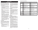
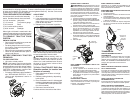
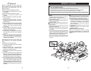
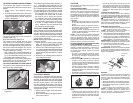
REEMPLAZAR LA BATERIA
ADVERTENCIA: No haga cortocircuito con los
terminales de la batería al permitir que una llave
de tuerca o cualquier otro objeto entre en contacto
con ambos terminales a la misma vez. Antes de
ins ta lar la batería remueva las pulseras de metal,
los relojes de pulsera de met al, los anillos, etc.
El terminal positivo tiene que conectarse primero
para evitar las chispas debido a la conexión a
tierra por accidente.
1. Levante el asiento a la posición elevada.
2. Desconecte el cable de la batería NEGRO (A)
primero y luego el cable de la batería ROJO
y remueva la batería del tractor.
3. Instale la nueva batería con los términos en
misma posición como la batería vieja.
4. Primero, conecte el cable de la batería ROJO
(B) con el terminal positivo (+) con el perno
hexagonal y la tuerca según se muestra.
Apriételos en forma segura. Deslize la cubi-
erta terminal (C) sobre el terminal.
5. Conecte el cable de conexión a tierra NE GRO
al terminal negativo (-) con el perno hex ag o nal
y la tuerca que queden. Apriételos en forma
segura.
6. Sierre el capo.
(Positivo)
Cable
rojo
(Negativo)
Cable negro
02954
A
B
C
PARA CAMBIAR LA BOMBILLA DE LA LUZ
DELANTERA
1. Levante el capota.
2. Tire el sujetador de la bombilla fuera del
agujero en la parte trasera del enrejado.
3. Cambie la bombilla en el sujetador y empuje
el sujetador de la bombilla, en forma segura,
hacia atrás en el agujero en la parte trasera
del enrejado.
4. Cierre el capota.
ENTRECIERRE Y RELÉS
El alambrado suelto o dañado puede producir el
mal fun cio na mien to de su tractor, o que deje de
funcionar, o le impida el arrancar.
• Revise el alambrado.
PARA CAMBIAR EL FUSIBLE
Cámbielo por un fusible tipo enchufable de 30
amps, tipo au to mo triz. El sujetador del fusible
está ubicado detrás del tablero.
PARA REMOVER EL CONJUNTO DEL CAPOTA
Y DEL ENREJADO
1. Levante el capota.
2. Desabroche el conector del alambre de las
luces delanteras.
3. Párese delante del tractor. Agarre el capota
en los lados, inclínelo un poco hacia el motor
y sáquelo del tractor.
4. Para volver a instalar el capota, asegúrese
de volver a conectar el conector del alambre
de las luces.
04020
Capota
Conector del
alambre de
las Luces
Delanteras
MOTOR
PARA AJUSTAR EL CABLE DE CONTROL
DE LA ACELERACIÓN
El control de la aceleración ha sido preajustado
en la fábrica y no debería necesitar ajustes. Re-
vise los ajustes que se describen a continuación,
antes de soltar el cable. Si el ajuste es necesario,
vea de manual de motor.
PARA AJUSTAR EL CONTROL DE
ESTRANGULA CIÓN
El control de la estrangulación ha sido preajusta-
do en la fábrica y no debería necesitar ajustes.
PARA AJUSTAR EL CARBURADOR
El carburador ha sido preajustado en la fábrica
y no debería necesitar ajustes. Sin embargo, se
pueden necesitar ajustes de menor importancia
para compensar por las diferencias en el combus-
tible, temperatura, altura o carga. Si el carburador
ne ce si ta ajustes, vea de manual de motor.
TRANSMISIÓN
REMOCIÓN/REEMPLAZO DE LA
TRANSMISIÓN
Si por acaso su transmisión debe ser removida
para servicio o reemplazo, debe ser purgada
después de la reinstalación y antes de operar el
tractor. Vea “PUR GAR LA TRANSMISIÓN” en la
sección de la Operación de este manual.