


46
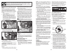
REVISIÓN DE LA PRESIÓN DE LAS
LLANTAS
Las llantas en su unidad fueron infladas de-
masiado en la fábrica por razones de envío. La
presión de las llantas correctas es importante
para obtener el mejor rendimiento en el corte.
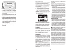
• Reduzca la presión de los neumáticos a la PSI
que se indica en estos.
REVISIÓN DE LA NIVELACIÓN DEL
CONJUNTO
Para obtener los mejores resultados en el corte,
la caja de la segadora tiene que estar nivelada
en la forma adecuada. Vea “PARA NIVELAR
LA CAJA DE LA SEGADORA” en la sección de
Servicio y Ajustes de este manual.
REVISIÓN DE LA POSICIÓN ADECUADA
DE TO DAS LAS CORREAS
Vea las figuras que aparecen para cambiar las
correas de impulsión de la cuchilla de la sega-
dora y de movimiento en la sección de Servicio y
Ajustes de este manual. Verifique que las correas
sigan su paso correcto.
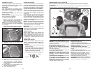
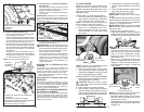
U
D
C
C. Eslabones de levantamiento traseros
D. Escuadra trasera derecha de la cortadora
de césped
U. Agujero
M. Polea del
embrague del
motor
motor
M
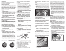
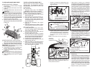
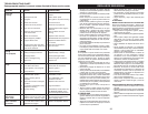
8. Instale el eslabón delantero (E)
• Gire el volante hasta ubicar las ruedas dere-
chas en posición de avance.
• Desde la parte delantera del tractor, inserte el
extremo de varilla del eslabón delantero (E) a
través del agujero delantero de la escuadra
de suspensión delantera del tractor (F).
• Muévase hasta el lado izquierdo de la corta-
dora e inserte un resorte de retención grande
(G) a través del agujero del eslabón delantero
(E) detrás de la escuadra de suspensión
delantera (F).
• Inserte el otro extremo del eslabón (E) en el
agujero de la escuadra derecha de la cortadora
de césped (H) y asegure con una arandela y
un resorte de retención pequeño (J).
NOTA: requiere levantar la plataforma.
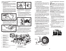
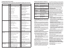
9. Instale la correa en la polea del embrague
del motor (M)
• Desenganche la varilla tensora de la correa
(K) de la escuadra de bloqueo (L). (Vea el
diagrama completo en la página 1.)
• Instale la correa en la polea del embrague
del motor (M)
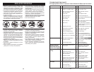
IMPORTANTE: Verifique que la trayectoria de
la correa sea correcta en todos los surcos de la
polea de la cortadora de césped y debajo de las
cubiertas de mandril.
• Enganche la varilla tensora de la correa (K)
en la escuadra de bloqueo (L).
PRECAUCIÓN: la varilla tensora de la correa
está accionada por resorte. Sostenga la varilla
firmemente apretada y engánchela lentamente.
• Eleve la palanca de levantamiento del ac-
cesorio hasta la posición máxima.
• Si es necesario, ajuste las ruedas calibrado-
ras antes de hacer funcionar la cortadora de
césped como se muestra en el manual del
propietario/operador. Verifique las ruedas
calibradoras, el nivel de la plataforma y los
ajustes del rastrillo.
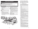
Ubicación
Del Eslabón
Delantero
M
J
E
G
F
H
E. Conjunto de eslabones de levantamiento
delanteros
F. Escuadra de suspensión delantera
H. Escuadra de la cortadora de césped delantera
J. Resorte de retención pequeño
M. Polea del embrague del motor
27
TO LEVEL MOWER
Make sure tires are properly inflated to the
PSI shown on tires. If tires are over or under
inflated, it may affect the appearance of your
lawn and lead you to think the mower is not
adjusted properly.
VISUAL SIDE-TO-SIDE ADJUSTMENT
1. With all tires properly inflated and if your
lawn appears unevenly cut, determine
which side of mower is cutting lower.
NOTE: As desired, you can raise the low
side of mower or lower the high side.
2. Go to side of mower you wish to adjust.
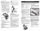
3. With a 3/4" or adjustable wrench, turn
lift link adjustment nut (A) to the left to
lower the mower, or, to the right to raise
the mower.
02966
A
A
02548
B
B
NOTE: Each full turn of adjustment nut will
change mower height about 3/16".
4. Test your adjustment by mowing some
uncut grass and visually checking the
appearance. Readjust, if necessary, until
you are satisfied with the results.
PRECISION SIDE-TO-SIDE ADJUSTMENT
1. With all tires properly inflated, park tractor
on level ground or driveway.
CAUTION: Blades are sharp. Protect
your hands with gloves and/or wrap blade
with heavy cloth.
2. Raise mower to its highest position.
3. At both sides of mower, position blade at
side and measure the distance (A) from
bottom edge of blade to the ground. The
distance should be the same on both sides.
4. If adjustment is necessary, see steps 2
and 3 in Visual Adjustment instructions
above.
5. Recheck measurements, adjust if neces-
sary until both sides are equal.
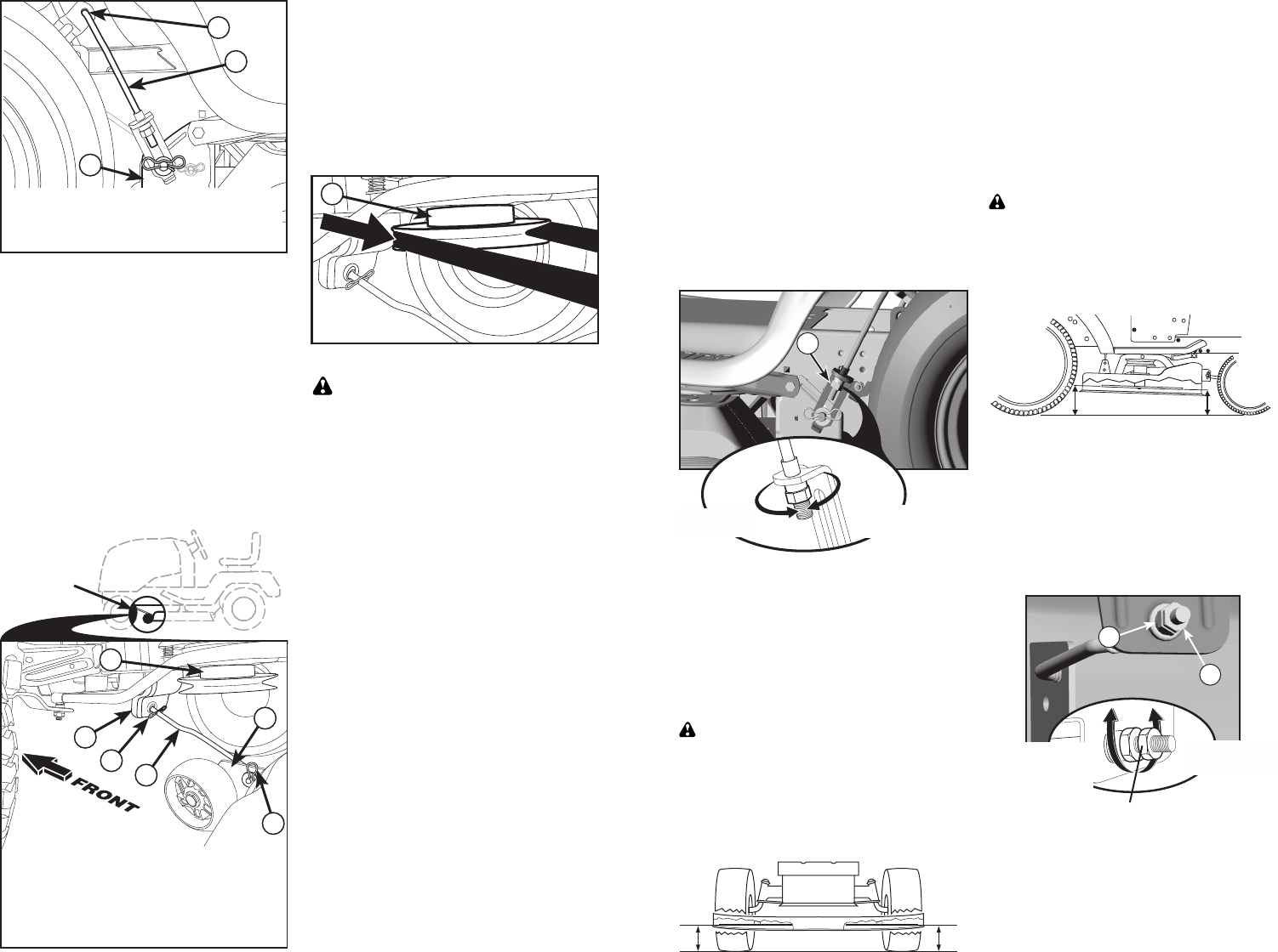
FRONT-TO-BACK ADJUSTMENT
IMPORTANT: Deck must be level side-
to-side.
To obtain the best cutting re sults, the mower
blades should be adjusted so the front tip is
1/8" to 1/2" lower than the rear tip when the
mower is in its highest position.
CAUTION: Blades are sharp. Protect
your hands with gloves and/or wrap blade
with heavy cloth.
• Raise mower to highest position.
• Position any blade so the tip is pointing
straight forward. Measure distance (B) to
the ground at front and rear tip of the blade.
• If front tip of blade is not 1/8" to 1/2" lower
than the rear tip, go to the front of tractor.
• With an 11/16" or adjustable wrench,
loosen jam nut A several turns to clear
adjustment nut B.
• With a 3/4" or adjustable wrench, turn
front link adjustment nut (B) clockwise
(ltighten) to raise the front of mower, or,
counterclockwise (loosen) to lower the
front mower.
NOTE: Each full turn of the adjustment nut
will change mower height about 1/8".
• Recheck measurements, adjust if neces-
sary until front tip of blade is 1/8" to 1/2"
lower than the rear tip.
• Hold adjustment nut in position with wrench
and tighten jam nut securely against ad-
justment nut.
0
2
9
4
8
A
Turn nut left
to lower mower
Turn nut right
to raise mower
B
A
02950
Loosen jam nut A first
Tighten adjust nut
B to raise mower
Loosen adjust
nut B to lower
mower