


44
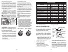
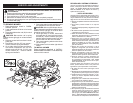
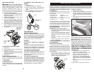
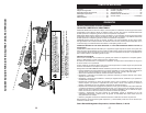
4. Deslice la cortadora de césped debajo del
tractor
• Lleve la correa hacia adelante y verifique que
su trayectoria sea correcta en todos los surcos
de la polea de la cortadora de césped.
NOTA: asegúrese de que los brazos de suspen-
sión lateral de la cortadora de césped (A) estén
orientados hacia adelante antes de deslizar la
cortadora de césped debajo del tractor.
E
A
M
F
B
K
C
C
S
W
H
D
D
L
A. Brazos De Suspensión
Lateral De La
Cortadora De Césped
B. Resorte De Retención
C. Eslabones De
Levantamiento Traseros
D. Escuadra Trasera
Derecha De La
Cortadora De Césped
E. Conjunto De Eslabones
De Levantamiento
Delanteros
F. Escuadra De
Suspensión Delantera
H. Escuadra De La
Cortadora De Césped
Delantera
I. Escuadra Trasera Izquierda De La Cortadora De
Césped
K. Varilla Tensora De La Correa
L. Escuadra De Bloqueo
Y
Z
W
H
X
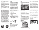
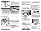
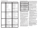
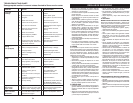
H. Escuadra de la cortado-
ra de césped delantera
W. Rueda calibradora
delantera
Parte Delantera
Parte Trasera
Motor
Transeje
Q. Blindaje
deflector
Q
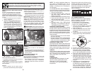
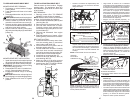
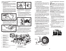
INSTALE LA SEGADORA Y LA CORREA
DE TRANSMISIÓN
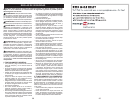
1. Accione la palanca del freno de estaciona-
miento (P) y la palanca de levantamiento
del accesorio inferior (N).
• Presione el pedal de embrague/freno
completamente hasta abajo y manténgalo
apretado.
• Tire y mantenga la palanca del freno de esta-
cionamiento (P) hacia arriba, libere la presión
del pedal de embrague/freno y, luego, suelte la
palanca del freno de estacionamiento. El pedal
debe permanecer en posición de frenado.
Asegúrese de que el freno de estacionamiento
mantendrá asegurado el tractor.
PRECAUCIÓN: La palanca de levantamiento
(N) está accionada por resorte. Sosténgala
firmemente apretada, bájela lentamente y
engánchela en la posición más baja. La
palanca de levantamiento se encuentra en
el lado izquierdo de la defensa.
2. Arme la rueda calibradora delantera (W) en
la parte delantera de la cortadora de césped
X. Perno con resalto
Y. Arandela de 1¼
Z. Tuerca de seguri-
dad de 3/8-16
3. Gire el volante hacia la izquierda y ubique
la cortadora de césped en su lugar
• Gire el volante completamente hacia la
izquierda y ubique la cortadora de césped
en el lado derecho del tractor con el blindaje
deflector (Q) a la derecha.
M. Polea Del Embrague Del Motor
Q. Blindaje Deflector
S. Barra Antibalanceo
W. Rueda Calibradora Delantera
N
N. Palanca de
levantamiento
P. Palanca del freno
de estacionamiento
P
29
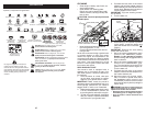
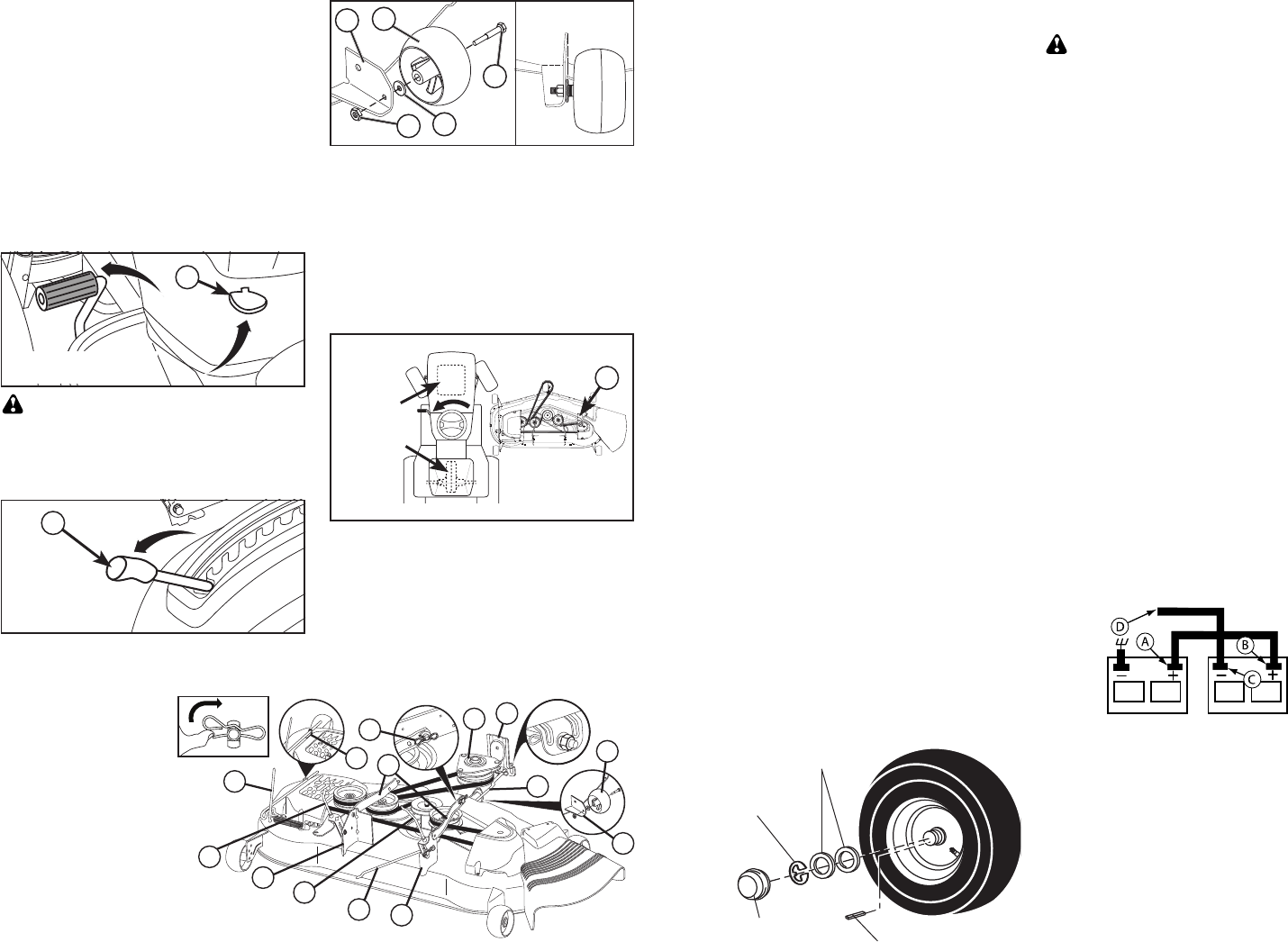
TO START ENGINE WITH A WEAK BAT-
TERY
WARNING: Lead-acid batteries gen er-
ate ex plo sive gases. Keep sparks, flame
and smoking ma te ri als away from bat ter ies.
Always wear eye pro tec tion when around
batteries.
If your battery is too weak to start the engine, it
should be recharged. (See "BATTERY" in the
MAINTENANCE section of this man u al).
If “jumper ca bles” are used for emer gen cy
starting, follow this pro ce dure:
IMPORTANT: Your tractor is equipped with
a 12 volt system. The other vehicle must also
be a 12 volt system. Do not use your tractor
battery to start other vehicles.
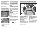
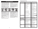
TO ATTACH JUMPER CABLES
1. Connect one end of the RED cable to the
POSITIVE (+) terminal of each battery(A-
B), taking care not to short against tractor
chassis.
2. Connect one end of the BLACK ca ble
to the NEGA TIVE (-) terminal (C) of fully
charged battery.
3. Connect the other end of the BLACK
cable (D) to good chassis ground, away
from fuel tank and bat tery.
TO REMOVE CABLES, REVERSE
ORDER
1. BLACK cable first from chassis and then
from the fully charged battery.
2. RED cable last from both batteries.
Weak or Dead
Battery
Fully Charged
Battery
0
0663
Retaining
Ring
Washers
Axle Cover
Square Key (Rear
Wheel Only)
TO REMOVE WHEEL FOR REPAIRS
1. Block up axle securely.
2. Remove axle cover, retaining ring and
washers to allow wheel removal (rear
wheels have a square key - Do not lose).
3. Repair tire and reassemble.
NOTE: On rear wheels only: align grooves in
rear wheel hub and axle. Insert square key.
4. Replace washers and snap retaining ring
securely in axle groove.
5. Replace axle cover.
NOTE: To seal tire punctures and pre vent
flat tires due to slow leaks, purchase and
use tire sealant from Sears. Tire sealant also
pre vents tire dry rot and corrosion.
FRONT WHEEL TOE-IN/CAM BER
Your new tractor front wheel toe-in and cam-
ber is set at the factory and is normal. The
front wheel toe-in and camber are not adjust-
able. If damage has occurred to affect the
factory set front wheel toe-in or camber, con-
tact a Sears or other qualified service center.
TO CHECK BRAKE
If tractor requires more than five (5) feet to
stop at highest speed in high est gear on a
level, dry concrete or paved surface, then
brake must be serviced.
You may also check brake by:
1. Park tractor on a level, dry concrete or
paved surface, depress brake pedal all
the way down and engage parking brake.
2. Disengage transmission by placing
freewheel control in “transmission dis-
engaged” position. Pull freewheel control
out and into the slot and release so it is
held in the disengaged position.
The rear wheels must lock and skid when
you try to manually push the tractor forward.
If the rear wheels rotate, then the brake
needs to be serviced. Contact a Sears or
other qualified service center.