


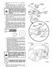
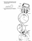

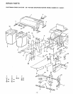

10. Place L.H, baffle (Fig. 4) on lip of mower housing.
Secure L.H. runner to L.H. baffle and mower hous-
ing using: two 5/16 carriage bolts and two 5/16
locknuts (shown full size below). NOTE: Do not
tighten. L.H, baffle and hardware furnished with
bagger.
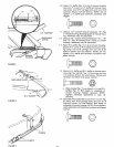
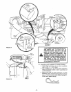
R.H. FOOTREST
DISCHARGE
GUARD
MOWER
HOUSING
FIGURE 5
FIGURE 6
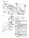
11. Using a 1/2" wrench remove hardware "'D" (Fig.
5 - Inset) securing discharge guard to mower hous-
ing. Hardware may be discarded,
1 2, Using a 1/2"' wrench remove hardware "'A", "'B"
and "'C" (Fig, 6) securing R.H. runner to mower
housing. Hardware may be discarded.
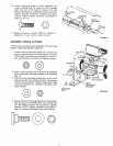
1 3. Place R.H. baffle (Fig. 4) on lip of mower housing.
Secure R.H, runner to R,H. baffle and mower hous-
ing using: one 5/16 carriage bolt and one 5/16
locknut (shown full size below). NOTE: Do not
tighten. R.H, baffle and hardware furnished with
grass catcher.
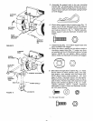
14.
Secure L,H. baffle and R.H. baffle to mower hous-
ing using: four clamps, four 1/4 hex bolts and four
1/4 Iocknuts (shown futl size below). Clamps and
hardware furnished with grass catcher,
I tlll!!lllltllllJi
a. Place clamps (Fig. 7) overholes in L.H. and R, H.
baffles (Fig, 7). Bolt heads to underside of
mower housing, Tighten securely. NOTE:
Tighten hardware assembled in step 10
securely.
1 5. Assemble latch assembly to top of R.H. runner (Fig.
8) using: two 5/16 carriage bolts and two 5/16
Iocknuts (shown full size below). Bolt heads to
underside of mower housing, NOTE: Do not tighten.
Latch assembly and hardware furnished with grass
catcher,
©
CLAMPS
FIGURE 7 - 6 -