


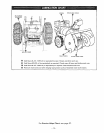
cable is loose and sags when lever is pushed all the way
down to last notch. To adjust cable:
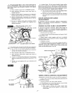
A. Loosen bottom nut on power clutch cable (figure 4)
and tighten top nut until lever will reach top notch.
B. Loosen top nut and tighten bottom nut to remove
looseness from cable when lever is in bottom
notch.
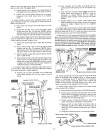
5_ Attach throttte control lever assembly (other end of
cable attached to left rear of engine} to control panel as
shown in figure 4 by:
A. Insert lever up through slot in left side of control
panel.
B. Attach with two No. 10 x 1/2inch hex washer t_ead
screws and two No. 10 Iocknuts. NOTE: Before
tightening screws and locknuts, check to make sure
that lever does not rub side of slot in control panel.
6. Attach impeller!auger drive control lever (other end of
cable is attached on right side of unit below gas tank) to
controt panel as shown in figure 4 by:
A. Insert lever up through slot in right side of control
panel
B. Attach with two No. 10 x 1/2inch hex washer head
screws and two No. 10 {ocknuts. NOTE: Before
tightening screws and ]ocknuts, check to make sure
that lever does not rub side of slot in control panel.
C. Attach impeller/auger drive control cable to handle
with a cable clamp.
D. Place a knob onto throttle and impeller/auger drive
controi tevers and tap firmly with a hammer until
knobs will not pull off. CAUTION: Knobs are made
of plastic and will break if hit too hard. A plastic or
rawhide hammer is recommended.
7. A power clutch cabte is attached under belt cover in
front of engine. Cable shoutd wrap around left side of engine
and under carburetor. Attach cable by:
A. Remove top nut from threaded end of cable and
slide cable through slot in lower edge of control
panel.
B. Push threaded end of cable up through hole in
control panel and replace, but do not tighten, top
nut.
C, Hook loop end of power clutch cable over pin on
power clutch lever (figure 4). NOTE: It may be
necessary to loosen bottom nut on cable to
lengthen cable enough to hook over pin on clutch
handle.
D. Tighten bottom nut on power clutch cabEe until
cable stop (figure 4) just clears top end of threaded
portion of cable. Tighten top nut to complete
assembly.
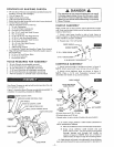
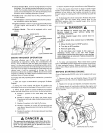
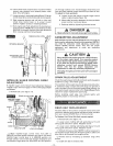
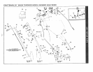
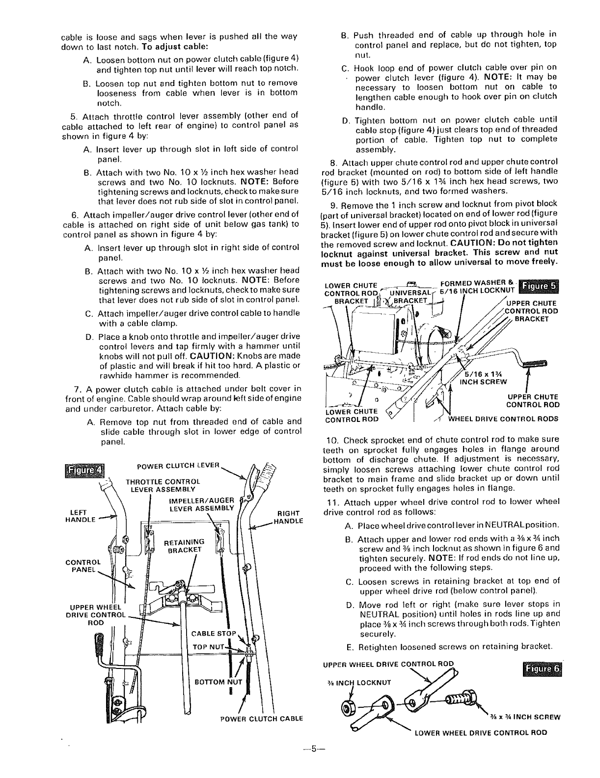
8. Attach upper chute control rod and upper chute control
rod bracket (mounted on rod) to bottom side of left handle
(figure 5) with two 5/16 x 13/4 inch hex head screws, two
5/16 inch Iocknuts, and two formed washers.
9. Remove the 1 inch screw and locknut from pivot block
(part of universal bracket) located on end of lower rod (figure
5). insert lower end of upper rod onto pivot block in universal
bracket (figure 5) on lower chute control rod and securewith
the removed screw and Iocknut. CAUTION: Do not tighten
Iocknut against universal bracket. This screw and nut
must be loose enough to allow universal to move freely.
FORMED WASHER 8,. _jl_._
LOWER CHUTE _._._ 5/16 INCH LOCKNUT
CONTROL ROD
BRACKET BRACKET _ CHUTE
BRACKET
5/16x1¾
INCH SCREW
UPPER CHUTE
CONTROL ROD
LOWER CHUTE
CONTROL ROD WHEEL DRIVE CONTROL RODS
10. Check sprocket end of chute control rod to make sure
teeth on sprocket fully engages holes in flange around
bottom of discharge chute. If adjustment is necessary,
simply loosen screws attaching lower chute control rod
bracket to main frame and sIide bracket up or down until
teeth on sprocket fully engages holes in flange.
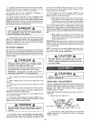
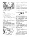
1 I. Attach upper wheel drive control rod to lower wheel
drive control rod as follows:
A. Place wheel drive control lever in NEUTRALposition.
B. Attach upper and lower rod ends with a _ x 3,4inch
screw and 3/8inch Iocknut as shown in figure 6 and
tighten securely. NOTE: If rod ends do not line up,
proceed with the following steps.
C. Loosen screws in retaining bracket at top end of
upper wheel drive rod (below control panel).
D. Move rod left or right (make sure lever stops in
NEUTRAL position) until holes in rods line up and
place 3,_x 3,4inch screws through both rods. Tighten
securely.
E. Retighten loosened screws on retaining bracket.
UPPER WHEEL DRIVE CONTROL ROD
3/S _NCH LOCKNUT _
-- ox ,NcNscREw
LOWERWHEEL DRIVE CONTROL ROD
--5 m