


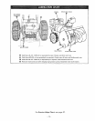

SKID and GAGE WHEEL
(Height) ADJUSTMENT
A CAUTION A
For packing purposes, the gage wheels on this unit
were adjusted all the way up to lowest height
position, Adjust height as instructed below before
using snow thrower,
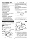
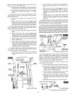
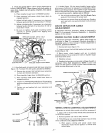
This unit is equipped with a pair of skids mounted on the back
side of the auger housing and a pair of gage wheels located
on the outside of the auger housing. Both the skids andgage
wheels are used to elevate the front of the machine up to 1
inch. Figure 7 shows both parts.
When removing snow from hard surface area such as paved
driveway or sidewalk, we suggest use of gage wheels only, to
elevate front of machine to desired height. To change height
of gage wheels:
1. Remove Iocknut on shoulder bolt through gage wheel
(figure 7).
2. Relocate shoulder bolt into hole representing desired
height and replace Iocknut.
3. Set wheel on other side at same height.
4. Loosen, pull up and tighten skids to full UP position
after gage wheels have been set.
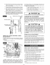
AUGER
HOUSING
LOW SE'n'IN G
HIGH SETTING
LOCKNUT
SKID
,INT|NG
SCREW
FLATWASHER
GAGE WHEEL
SHOULDER BOLT
SKID
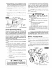
The operation of any powered outdoor equipment can result
in foreign objects being thrown into the eyes, which can
result in severe eye damage. Always
wear safety glasses or eye shields
before beginning snow thrower opera-
tion. We recommend Wide Vision
Safety Mask for over spectacles or
standard safety glasses, available at
SEARS Retail or Catalog Stores.
Familiarize yourself with the equipment and with the
Operational Precautions,
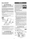
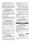
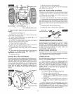
OPERATING CONTROLS
Operating controls (figures 8 & 9) and their functions are as
follows:
• Power Clutch Lever - The power clutch lever controls
forward or reverse motion of the unit when the wheel
drive control lever is in the appropriate position. When
the operator's hand is removed from the power clutch
lever, tension is removed from drive belts, therefore
unit motion and impeller/auger rotation stop. Engage
slowly but firmly and all the way down against hand
grip.
• Impeller/Auger Drive Control Lever - Used to disen-
gage power to impeller/auger without interfering with
power to drive wheels. Pull up to engage. Push down to
disengage. NOTE: Power clutch lever must be in re-
leased (disengaged) position before impeller/auger
lever position is changed.
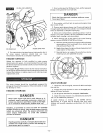
e Throttle Control Lever - This snowthrower is equipped
with a control panel mountedthrottle control lever used
to control speed of engine, There are three positions on
the throttle control - Stop - Slow - Fast.
O Wheel Drive Control Lever -Used to select desired unit
speed or direction. Choice of five forward speeds, neu-
tral and reverse.
_) Chute Deflector Lever- The distance snow will be dis-
charged can be adjusted by raising chute deflector
(figure 8) for more distance, or lowering for less dis-
tance. Pull lever up to top notch for most distance. Push
lever down to bottom notch for least distance.
When removing snow from rock or unpaved construction;
we suggest you raise the front of the machine with the skids.
To raise the machine with the skids:
1. Loosen the skid mounting nuts (figure 7) and push the
skid down until the front of the machine is raised to desired
height. Retighten mounting nuts.
2. Set skid on other side at same height. NOTE: Be sure
that front of unit is set at same height on both sides.
DANGER
Be certain to maintain proper ground clearance for
your particular area to be cleared. Objects such as
gravel, rocks or other debris, if struck by the
impeller/auger, may be thrown with sufficient force
to cause personal injury or property damage.
DANGER
Do not put hands in or near the deflector chute while
the engine is running.
IMPELLER/AUGER CONTROL LEVER
THROTTLE CONTROL LEVER
DEFLECTOR LEVER
L DRIVE CONTROL LEVER
CHUTE
POWER
CLUTCH
LEVER
%
OIL FILL CAP
& DIPSTICK
--6--