


CONTENTS OF SHIPPING CARTON
1 - 24 inch Snow Thrower (completely assembled except for
handles, controls and headlight),
1 - Can of Engine Oil
1 - Upper Chute Control Rod
1 - Left Hand Handle Assembly
1 - Right Hand Handle Assembly (with clutch lever attached)
I - Control Pane_ Assembly
1 - Bag of Assembly Parts Containing:
I - 3A inch Flatwasher
2 - 5/16 inch Split Lockwasher
10 - Formed (curved) Washers
4 - No. 10 x 1/2inch Hex Head Screws
4 - No. 10 Locknuts
2 - 5/16 x 5/8, inch Hex Head Screws
2 - 5/16 x 1 inch Hex Head Screws
8 - 5/16 x 13A inch Hex Head Screws
8 - 5/16 inch Locknuts
1 - 3/_x 3A inch Hex Head'Screws
1 - 3_ inch Locknut
1 - Cable C_amp (meta!)
2 - Knobs (for Throttle and Impeller/Auger Drive Levers)
1 - Bag of Shear Bolt Replacement Parts (Not used in assem-
bly) Containing:
3 - 5/16 x 13/_ inch Shear Bolts
3 - 5/16 inch Locknuts
I - Instruction Sheet
TOOLS REQUIRED FOR ASSEMBLY
1 - 3/8inch Wrench (or adjustable wrench)
1 - 5/16 inch Wrench (or adjustable wrench)
2 _ V2 inch Wrenches {or adjustable wrenches)
2 - 7/16 inch Wrenches (or adjustable wrenches)
2 - 9/16 inch Wrenches (or adjustable wrenches)
1 - Hammer (plastic or rawhide head recommended)
DANGER
The operation of any powered equipment can result
in foreign objects being thrown into the eyes, which
can result in severe eye damage. Always wear safety
glasses or eye shields while assembling or operating
Snow Thrower.
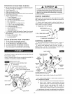
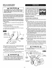
HANDLE ASSEMBLY
Right handle has a lever (power clutch) attached to upper
end. Nuts used to attach lower end of handles are attached to
inside of side frame.
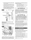
1. Attach right lower handle to side of side frame as
shown in figure 2. Handle grip should be tilted down and out
when handle is properly installed. "-
2. Repeat step 1 for left handle.
RIGHT HANDLE
FORMED WASHER
SIDE FRAME
5/16 x 1 INCH SCREW _
5/16 x % INCH SCREW L
5/,16 INCH SPLIT LOCKWASHER _
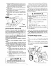
CONTROLS ASSEMBLY
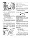
1. Attach control panel to handles as shown in figure 3.
NOTE: Attach panel with lower screw only on left side.
2. Attach chute deflector lever as shown in figure 3.
NOTE: Place a 5/16 inch flatwasher between lever
assembly and handle at top screw position.
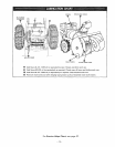
RIGHT HANDLE
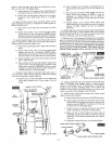
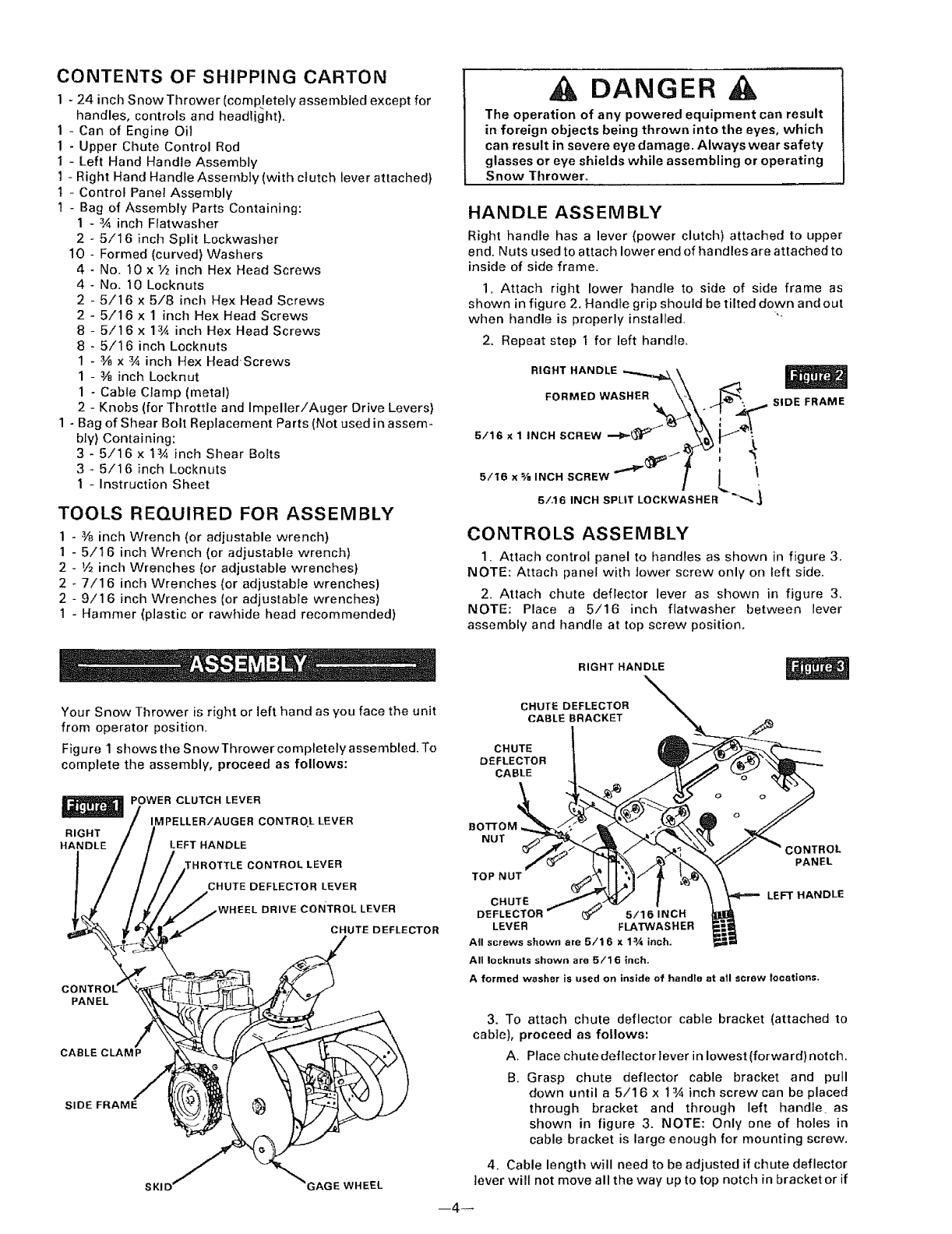
Your Snow Thrower is right or left hand as you face the unit
from operator position.
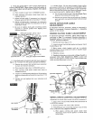
Figure 1 shows the Snow Thrower completely assembled. To
complete the assembly, proceed as follows:
POWER CLUTCH LEVER
IMPELLER/AUGER CONTRO.L LEVER
RIGHT
HANDLE LEFT HANDLE
,TTLE CONTROL LEVER
CHUTE DEFLECTOR LEVER
DRIVE coNTROL LEVER
CHUTE DEFLECTOR
PANEL
CABLE CLAMP
SIDE FRAME
_GAGE WHEEL
CHUTE DEFLECTOR
CABLE BRACKET
CHUTE
DEFLECTOR
CABLE
BOTTOM
NUT
TOP NUT
ONTROL
PANEL
CHUTE
r 5/16 INCH
LEVER FLATWASHER
All screws shown are 5/16 x 13,'_inch.
All Iocknuts shown are 5/16 inch.
A formed washer is used on inside of handte at all screw locations.
LEFT HANDLE
3. To attach chute deflector cable bracket (attached to
cable), proceed as follows:
A. Place chute deflector Iever in lowest (forward) notch.
B. Grasp chute deflector cable bracket and pull
down until a 5/16 x 1_'_ inch screw can be placed
through bracket and through left handle as
shown in figure 3. NOTE: Only one of holes in
cable bracket is large enough for mounting screw.
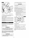
4. Cable length will need to be adjusted if chute deflector
lever wilf not move all the way up to top notch in bracket or if
--4--