


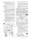
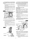
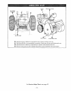
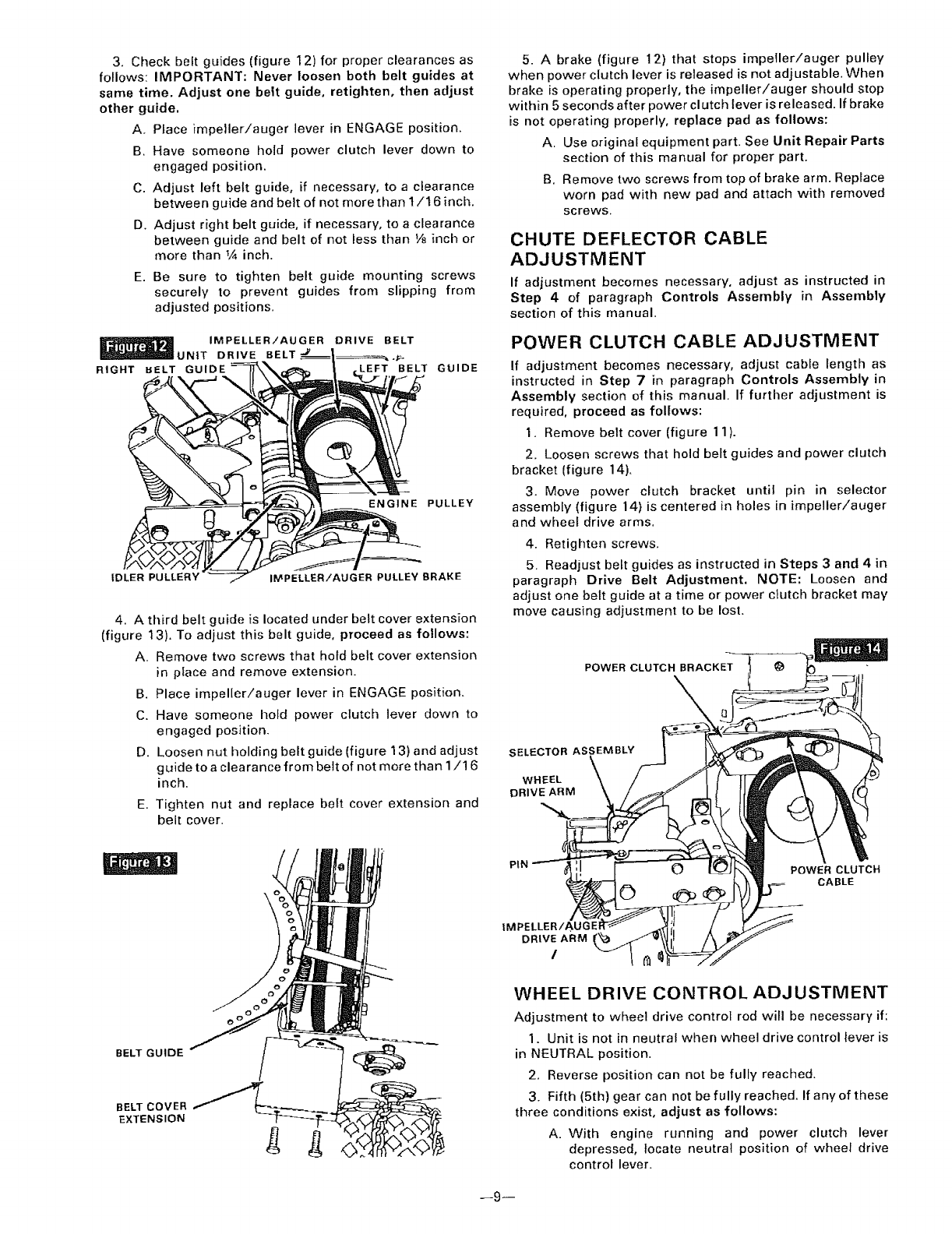
3. Checkbeltguides(figure12)forproperclearancesas
follows:IMPORTANT:Neverloosenbothbeltguidesat
sametime.Adjustonebeltguide,retighten, then adjust
other guide.
A, Ptace impeller!auger lever in ENGAGE position.
B. Have someone hold power clutch lever down to
engaged position.
C. Adjust left belt guide, if necessary, to a clearance
between guide and be}t of not more than 1/16 inch.
D. Adjust right belt guide, if necessary, to a clearance
between guide and belt of not less than V8 inch or
more than V_ inch.
E. Be sure to tighten belt guide mounting screws
securely to prevent guides from slipping from
adjusted positions.
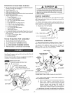
IMPELLER/AUGER DRIVE BELT
UNIT DRIVE BELT .._.
RIGHT BELT GUIDE ,LEFT BELT GUIDE
ENGINE PULLEY
IDLER PULLERY' IMPELLER/AUGER PULLEY BRAKE
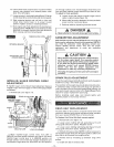
4. A third belt guide is located under belt cover extension
(figure 13). To adjust this belt guide, proceed as follows:
A. Remove two screws that hold belt cover extension
in place and remove extension.
B. Place impeller/auger lever in ENGAGE position.
C. Have someone hold power clutch lever down to
engaged position.
D. Loosen nut holding belt guide (figure 13) and adjust
guide to a clearance from belt of not more than 1/1 6
inch.
E. Tighten nut and replace belt cover extension and
belt cover.
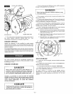
5. A brake (figure 12) that stops impeller/auger pulley
when power clutch lever is released is not adjustable. When
brake is operating properly, the impeller/auger should stop
within 5 seconds after power clutch lever is released. If brake
is not operating properly, replace pad as follows:
A. Use original equipment part. See Unit Repair Parts
section of this manual for proper part.
B. Remove two screws from top of brake arm. Replace
worn pad with new pad and attach with removed
screws.
CHUTE DEFLECTOR CABLE
ADJUSTMENT
If adjustment becomes necessary, adjust as instructed in
Step 4 of paragraph Controls Assembly in Assembly
section of this manual.
POWER CLUTCH CABLE ADJUSTMENT
If adjustment becomes necessary, adjust cable length as
instructed in Step 7 in paragraph Controls Assembly in
Assembly section of this manual. If further adjustment is
required, proceed as follows:
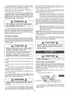
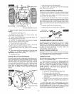
1. Remove belt cover (figure 11).
2. Loosen screws that hold belt guides and power clutch
bracket (figure 14).
3. Move power clutch bracket until pin in selector
assembly (figure 14) is centered in holes in impeller/auger
and wheel drive arms.
4. Retighten screws.
5. Readjust belt guides as instructed in Steps 3 and 4 in
paragraph Drive Belt Adjustment. NOTE: Loosen and
adjust one belt guide at a time or power clutch bracket may
move causing adjustment to be lost.
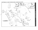
POWER CLUTCH BRACKET
\
SELECTOR ASSEMBLY
wHEEL
DRIVE ARM
BELT GUIDE
BELT COVER
EXTENSION
IMPELLER/AUGEF
DRIVE ARM
/
POWER CLUTCH
CABLE
WHEEL DRIVE CONTROL ADJUSTMENT
Adjustment to wheel drive controf rod will be necessary if:
1. Unit is not in neutral when wheel drive control lever is
in NEUTRAL position.
2. Reverse position can not be fully reached.
3. Fifth (5th) gear can not be fully reached. If any of these
three conditions exist, adjust as follows:
A. With engine running and power clutch lever
depressed, locate neutral position of wheel drive
control lever.
--9--