


......................ASSE..........L¥ ..............'.............
Hi, _lll,lllll, .......... -.. ........................ ii ll.i ill _,_
,,, .__..:. ...................... .......................................... .,_:..
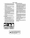
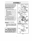
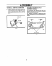
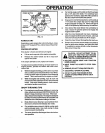
Figure1showsthe snowthmwerintheshippingposition.
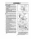
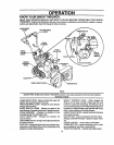
Figure2 showsthesnowthrowercomptetetyassembled,
Referenceto the righland left hand side ofthe snow
throwerisfrom the operator'spositionat the handle,,
TO REMOVE SNOW THROWER
FROM CARTON (See Fig. 1)
e Removethestaplesfromtop of carton.
o Locate thecrankassembly and placetheassembly
aside,
e Remove and discard the packing material from
aroundthe snowthrower,.
® Cut allfourcomersof thecartonfromtoptobottom
and lay laythe panelsflat,.
e Removethepackingmaterialfrom theshifterplate
and upperhandleassembly.
e Rollthesnowlhmweroffthecartonbypullingonthe
lowerhandle,,
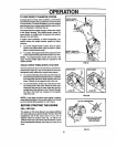
NOTE: Thedrive systemmay betightwhenyoufirstuse
yoursnowthrower.It loosensup as youuse ito
e To completeupperhandle installationand install
chutecrankassembly,see To InstallThe UpperHandle
and CrankAssemblyparagraphon page8.
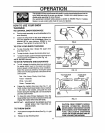
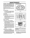
NOTE: Ifthecableshavebecomedisconnectedfromthe
clutchlevers,reinstallthe cablesas shownin Fig.3,
HOW TO SET UP YOUR SNOW
THROWER
o
Your snow throweris equippedwithheightadjust
skids (See Fig. 2) on the outsideof the auger
housing,,To adjust the skid height for different
conditions, seeToAdjustSkidHeightparagraphon
page 17._
CAUTION: IF YOU ARE REMOVING
,_ SNOW FROMANY ROCKY OR UNEVEN
SURFACE, RAISE THE FRONT OFTHE
SNOW THROWER BY MOVING THE
SKIDS DOWN. THIS WILL HEt.P TO PREVENT
ROCKS AND OTHER DEBRIS FROM BEING
PICKED UP AND THROWN BYTHE AUGER,
.............. _ ;; _ .......... ....... ±
LOWER HANDLE CONTROL PANEL
CLUTCH
CABLE
UPPER
HANDLE
ASSEMBLY
CRANK ASSEMBLY
CLUTCH
CABLES
CHUTE
DEFLECTOR
SHIFTER
FIG. 2
"Z" FITTING
TRACTION
DRt!/E
LEVER
FIG. 3
7