


9
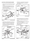
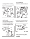
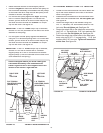
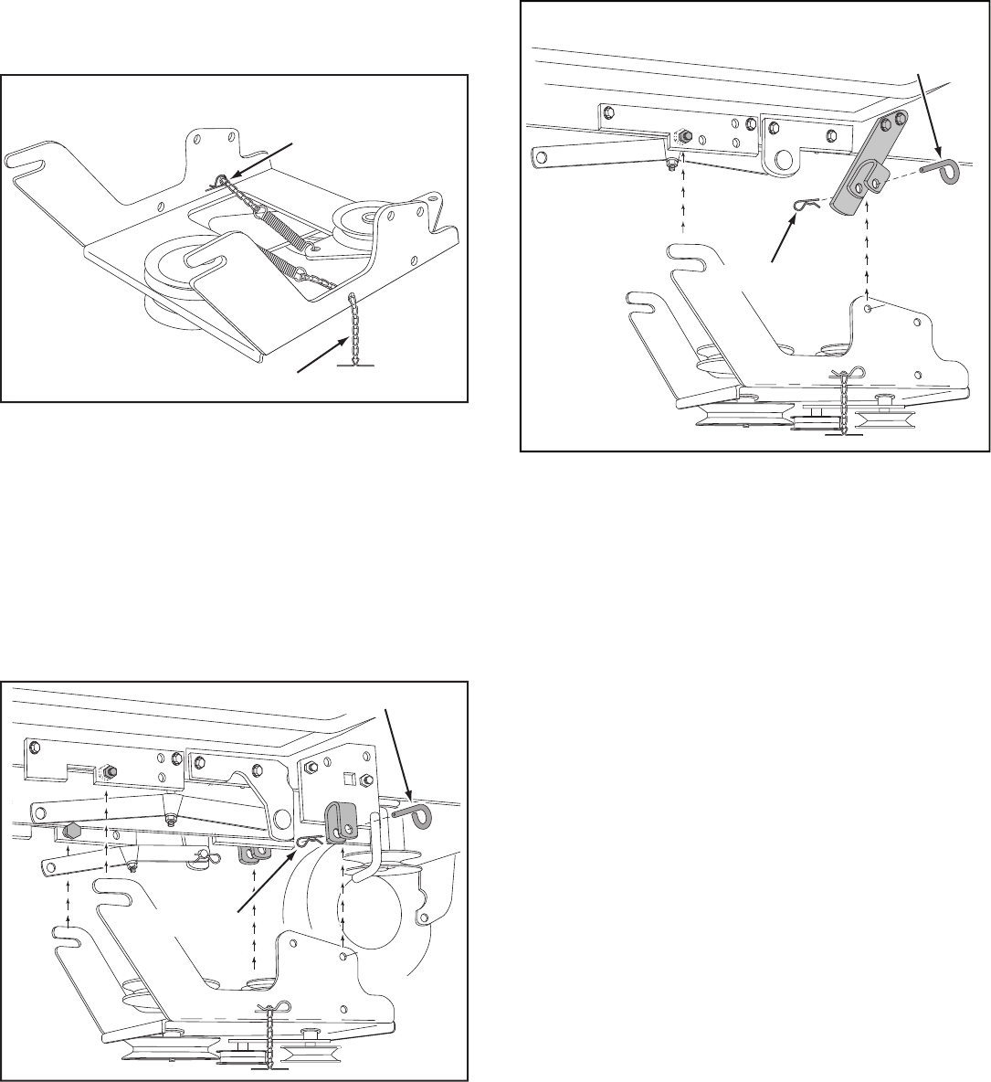
FIGURE 12 RIGHT SIDE VIEW
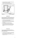
FIGURE 11
If your mower deck is 54" skip this paragraph.
• Attach the rear of the clutch/idler assembly to the
tractor frame by sliding the notched arms of the
assembly onto the shoulder bolts as sem bled to
the frame brackets. Lift the front of the assembly,
positioning the upper idler pulley so that it clears the
engine pulley. Attach the front of the assembly to the
hanger brackets using two pivot lock pins and two
hairpin clips. See fi gure 12.
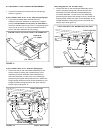
ATTACHING CLUTCH/IDLER ASSEMBLY
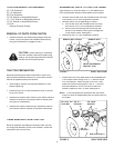
LINK #5 IN
L.H. CHAIN
R.H. CHAIN
• Connect the end link of each chain to the springs
shown in fi gure 11.
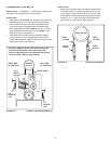
If your mower deck is 48" or 54" skip this paragraph.
• If you have a mower deck smaller than 48",
measure the outer di am e ter of the trac tor's engine
pulley.
If the di am e ter of the pulley is less than 6",
move the inside hairpin clip in the L.H. ad just ing chain
from link #8 to link #5. (Links are counted from the
end of the chain attached to the spring).
ENGINE PULLEYS LESS THAN 6" IN DI AM E TER
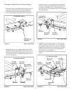
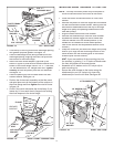
This paragraph for 54" mowers only.
• Attach the rear of the clutch/idler assembly to the
tractor frame by sliding the notched arms of the
assembly onto the shoulder bolts as sem bled to
the frame brackets. Lift the front of the assembly,
positioning the upper idler pulley so that it clears the
engine pulley. Attach the front of the assembly to the
hanger brackets using two pivot lock pins and two
hairpin clips. See fi gure 13.
HAIRPIN CLIP
PIVOT LOCK PIN
TRACTORS WITH 54" MOWER DECKS ONLY
FIGURE 13
HAIRPIN CLIP
PIVOT LOCK PIN