


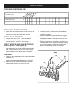
10
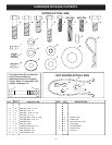
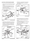
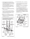
FIGURE 17 LEFT SIDE VIEW
• Remove the nylon tie which fastens the chute crank
rod to the crank support tube.
• Assemble the crank support tube (fl at side) to the two
brack ets on the left side of the thrower hous ing using
two 3/8" x 1-1/2" hex bolts, 3/8" lock wash ers and 3/8"
hex lock nuts. See fi gure 16.
• Attach the chute tilt control assembly to the top side
of the crank support tube using two 5/16" x 1-3/4"
carriage bolts, bowed washers, 5/16" lock washers
and 5/16" hex nuts. See fi gure 17.
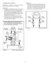
FIGURE 16 LEFT SIDE VIEW
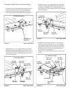
• Attach the chute crank assembly to the plastic bracket
on the left side of the thrower hous ing as shown in
fi gure 18. Use two 5/16" x 1" carriage bolts, 5/16" fl at
washers, 5/16" lock wash ers and 5/16" hex nuts.
Do
not tighten yet.
CRANK
SUPPORT
TUBE
3/8" LOCK
WASHER
3/8" HEX
LOCK NUT
3/8" x 1-1/2"
HEX BOLT
CHUTE CRANK ROD
CRANK SUPPORT TUBE
TILT CONTROL HANDLE
5/16" x 1-3/4"
CARRIAGE BOLT
BOWED WASHER
5/16" LOCKWASHER
5/16" HEX NUT
TILT
CONTROL
ASSEMBLY
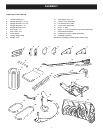
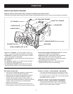
ASSEMBLY OF SNOW THROWER
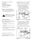
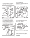
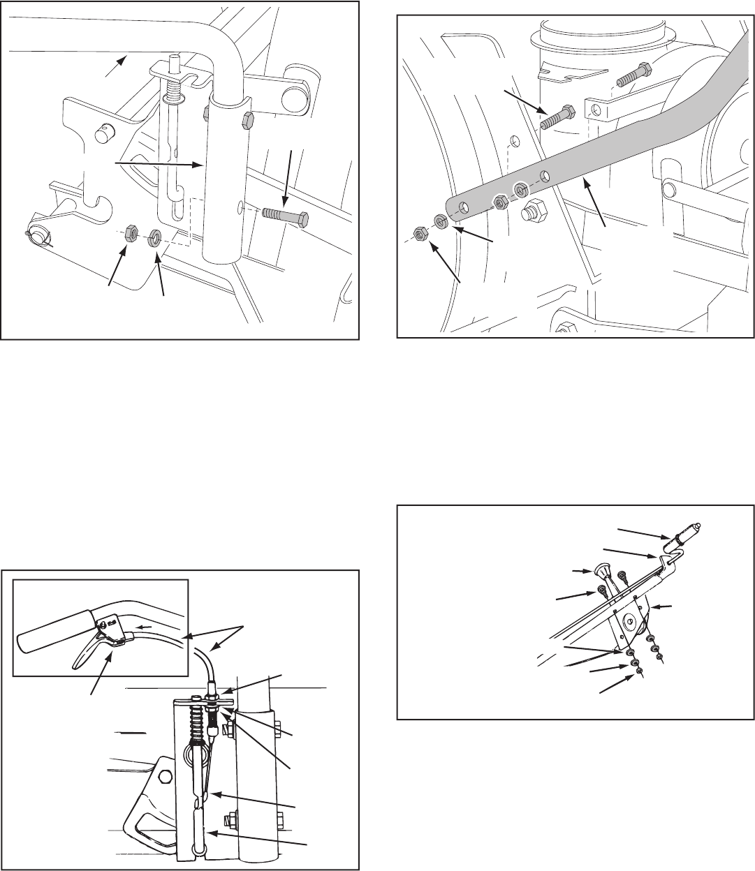
• Place the lift handle into the lift bracket on the right
side of the snow thrower. Fasten the handle to the
bracket using two 5/16" x 1-3/4" hex bolts, 5/16" lock
washers and 5/16" hex nuts. See fi gure 14.
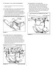
FIGURE 15 RIGHT SIDE VIEW
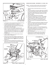
FIGURE 14 RIGHT SIDE VIEW
NOTE:
Be sure the lift release cable's plastic covering
remains inserted into the trigger assembly while
com plet ing the next step.
• Push the lift handle down into the locked position.
Insert the end of the cable wire into the hole in the
lift rod. Place the threaded fi tting into the slot in the
lift brack et, with one hex nut above and one hex
nut and the lock washer below the slot. Tight en the
nuts, ad just ing them to elim i nate slack in the cable
wire. See fi gure 15. Refer also to the Service and
Adjustments section on page 18 in this manual.
5/16" x 1-3/4"
HEX BOLT
5/16" LOCK
WASHER
5/16" HEX NUT
LIFT HANDLE
LIFT BRACKET
LIFT RELEASE
CABLE
HEX NUT
LOCK
WASHER
HEX NUT
CABLE
WIRE
LIFT
ROD
TRIGGER
ASSEMBLY