


13
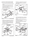
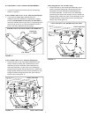
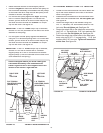
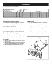
Hold this diagram above you while viewing the
Clutch/Idler Assembly from underneath the
tractor. Right and left in this diagram will be the
reverse of the view er's right and left.
FIGURE 23 VIEWED FROM UNDERNEATH
• Raise the snow thrower to the transport position.
• Place the
auger
belt around the bottom rear pulley on
auger belt around the bottom rear pulley on auger
the clutch/idler assembly and be tween the two pul leys
on the lower idler arm. Keep the fl at idler pulley to the
outside of the belt. See fi gure 23.
• Pull the fl at idler pulley against the
auger
belt using
auger belt using auger
the R.H. tension ad just ing chain. For correct belt
tension, pull the chain as far as the inside hairpin clip
will allow and then reinstall the
out side
1/8" hairpin
clip into the chain. See fi gure 23.
IMPORTANT:
If the R.H.
inside
hairpin clip is re moved,
reinstall it in link #4 (counted from the end of the chain
attached to the spring).
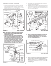
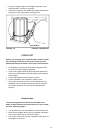
• Pull the upper fl at idler pulley against the
drive
belt
using the L.H. tension ad just ing chain. For correct belt
tension, pull the chain as far as the inside hairpin clip
will allow and then reinstall the
out side
1/8" hairpin
clip into the chain. See fi gure 23.
IMPORTANT:
If the L.H.
inside
hairpin clip is re moved,
reinstall it in link #8 on tractors with 6" diameter
engine pulleys or in link #5 on tractors with smaller
engine pulleys. (Links are count ed from the end of the
chain attached to the spring.)
FRONT
REAR
PULLEY
RIGHT SIDE
OF
TRACTOR
LEFT SIDE
OF
TRACTOR
1/8"
HAIRPIN
CLIP
R.H. TENSION
ADJUSTING CHAIN
(AUGER BELT)
L.H. TENSION
ADJUSTING CHAIN
(DRIVE BELT)
1/8"
HAIRPIN
CLIP
INSIDE
HAIRPIN
CLIP
INSIDE
HAIRPIN
CLIP
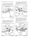
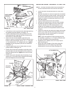
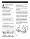
ATTACHING WEIGHT TRAY TO TRAC TOR
• Loosen the two hex bolts and nuts which fasten the
top of the tractor drawbar to the rear of the tractor
frame. See fi gure 24.
• Assemble the notched end of the side brace arms
down onto both loosened bolts.
Do not tighten yet.
See fi gure 24.
• Fasten the weight tray to the drawbar using two
3/8" x 1" hex bolts, 3/8" lock washers and 3/8" hex
lock nuts.
Do not tighten yet.
See fi gure 24.
• Fasten the weight tray to the side brace arms using
two 5/16" x 1" carriage bolts, 5/16" lock washers and
5/16" hex nuts.
Do not tighten yet.
See fi gure 24.
• Fasten the weight tray cross brace to the side brace
arms using two 5/16" x 1" carriage bolts, 5/16" lock
washers and 5/16" hex nuts.
Tighten all loose bolts
at this time.
See fi gure 24.
FIGURE 24 VIEWED FROM REAR
3/8" LOCK
WASHER
5/16" x 1"
CARRIAGE
BOLT
SIDE BRACE
ARM
WEIGHT TRAY
5/16" LOCK
WASHER
5/16" HEX NUT
3/8" x 1"
HEX BOLT
LOOSENED
NUT AND BOLT
CROSS
BRACE
3/8" HEX
LOCK NUT