


6
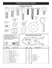
(2) 7/16" Wrenches
(2) 1/2" Wrenches
(2) 9/16" Wrenches
(1) 5/8" Wrench or Adjustable Wrench
(1) 11/16" Wrench or Adjustable Wrench
(1) 3/4" Wrench or Adjustable Wrench
(1) Knife
General Purpose Grease
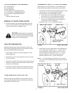
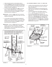
Right hand (R.H.) and left hand (L.H.) are determined
from the operators position while seated on the tractor.
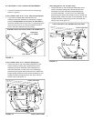
• Remove the hex bolt from the threaded hole at the top
front corner of R.H. front suspension bracket.
• Remove either a or b depending on tractor:
a. the hex bolt from the threaded hole at the top
rear corner of R.H. front suspension bracket.
b. the nut from the carriage bolt at the top rear
corner of the bracket, leaving the carriage bolt
in the tractor frame. See fi gure 1.
• Repeat for the L.H. front suspension bracket.
ASSEMBLING PARTS TO TRACTOR FRAME
TOOLS REQUIRED FOR ASSEMBLY
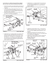
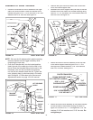
FIGURE 2 RIGHT SIDE VIEW
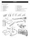
• Remove all parts and hardware pack ag es from the
carton. Lay out all parts and hardware and identify
using the illustrations on pages 4 and 5.
REMOVAL OF PARTS FROM CARTON
TRACTOR PREPARATION
Before proceeding with these instructions, refer to the
Service and Ad just ments section of your tractor owner's
manual for specifi c safety instructions.
• Allow engine, muffl er and exhaust defl ector to cool
before beginning.
• Remove any front or rear attachment which is mount-
ed to your tractor.
•
Remove the mower deck. Refer to your tractor owner's
manual for removal instructions. Mark all loose parts
and save for reassembly.
• Remove the tractor hood and grill assembly. Refer to
your tractor owner's manual for removal in struc tions.
CAUTION:
Before starting
to
assemble
the snow thrower, remove the spark plug
wire(s), set the parking brake and remove
the key from the tractor ignition.
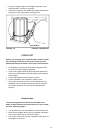
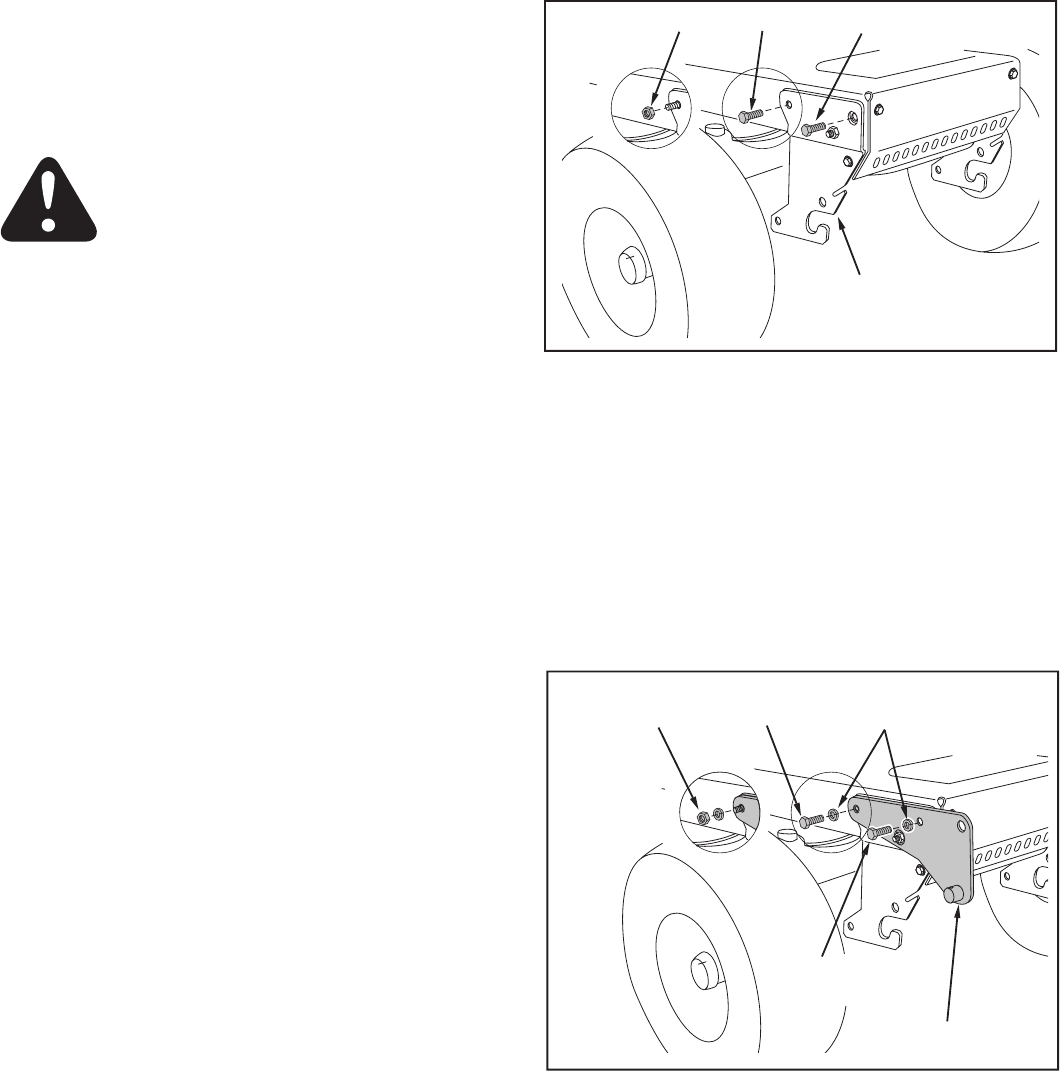
• Attach the front of the side plate to the threaded hole
in the tractor frame using a 3/8" x 1" hex bolt and a
3/8" lock washer. Attach the rear of the R.H. side
plate to the tractor using either a 3/8" x 1" hex bolt
and lock washer or a 3/8" hex lock nut and lock
washer. Repeat for the L.H. side. See fi gure 2.
NOTE:
If the side plates are removed from the tractor
frame, be sure to reassemble bolts and nuts back into
the frame.
FIGURE 1 RIGHT SIDE VIEW
ITEMS REMOVED FROM TRACTOR
Store all brackets and fasteners removed from the trac-
tor during the as sem bly of the snow thrower, unless the
in struc tions call for their use.
REMOVE BOLT
FRONT SUSPENSION
BRACKET (R.H.)
REMOVE NUT OR BOLT
3/8" HEX
LOCK NUT
3/8" LOCK
WASHER
3/8" x 1"
HEX BOLT
SIDE PLATE (R.H.)
3/8" X 1"
HEX BOLT
OR