


8
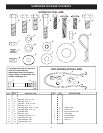
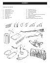
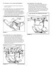
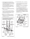
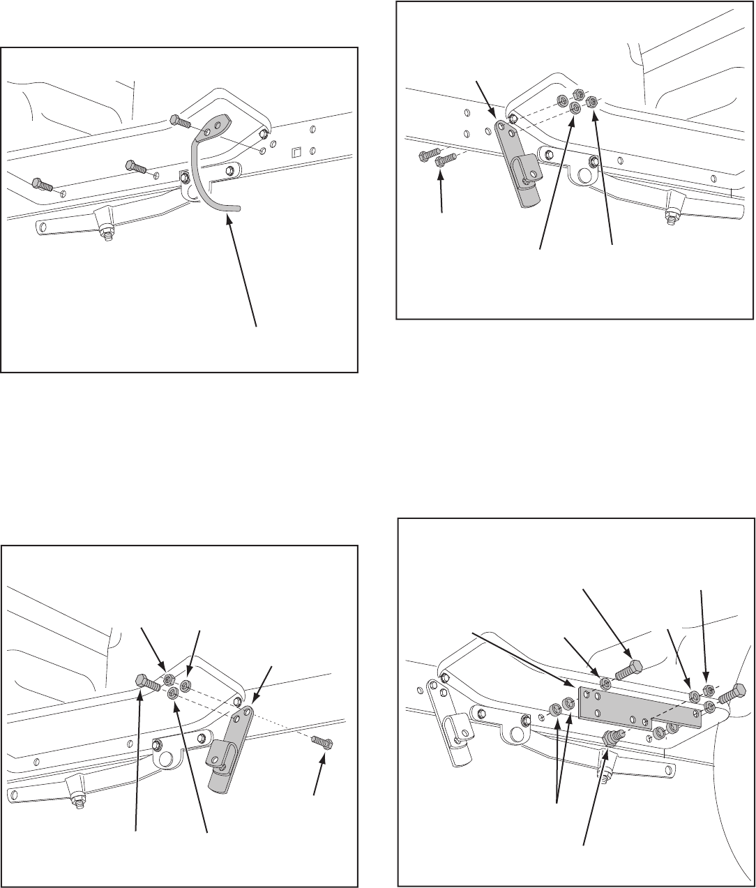
• Remove and store the mower stop bracket and bolt
from both sides of the tractor frame. See fi gure 3.
• Remove the two bolts from the bottom of the foot
rests on both sides of the tractor frame. See fi gure 7.
FIGURE 7 RIGHT SIDE VIEW
FIGURE 8 RIGHT SIDE VIEW
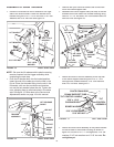
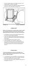
FIGURE 10 LEFT SIDE VIEW
FIGURE 9 LEFT SIDE VIEW
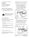
• Assemble the 54" R.H. hanger bracket to the holes
where the mower stop bracket was removed on the
right side of the tractor frame. Fasten with two 3/8" x
1" hex bolts, two 3/8" lock wash ers and one 3/8" hex
lock nut. See fi gure 8.
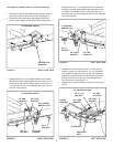
• Assemble a frame bracket to the L.H. foot rest as
shown in fi gure 10. Use two 3/8" x 1-1/4" hex bolts,
four spacers (2 per bolt) and two 3/8" lock wash ers.
• Assemble a shoulder bolt to the inside of the frame
bracket, securing it with a 3/8" lock wash er and a
3/8" hex lock nut. See fi gure 10.
• Repeat with a frame bracket on the R.H. side of the
tractor.
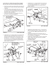
• Assemble the 54" L.H. hanger bracket to the holes
where the mower stop bracket was removed on the
left side of the tractor frame. Fasten with two 3/8" x 1"
hex bolts, two 3/8" lock wash ers and two 3/8" hex lock
nuts. See fi gure 9.
This page for tractors with 54" mower decks only.
MOWER STOP
BRACKET
3/8" x 1"
HEX BOLT
3/8" LOCK
WASHER
3/8" LOCK
WASHER
3/8" HEX
LOCK NUT
R.H. HANGER
BRACKET (54")
3/8" x 1"
HEX BOLT
3/8" LOCK
WASHER
L.H. HANGER
BRACKET (54")
3/8" x 1"
HEX BOLT
3/8" HEX
LOCK NUT
3/8" LOCK
WASHER
FRAME
BRACKET
3/8" x 1-1/4"
HEX BOLT
3/8" LOCK
WASHER
3/8" HEX
LOCK NUT
SHOULDER
BOLT
(2) SPACERS
54" MOWER DECKS
54" MOWER DECKS
54" MOWER DECKS
54" MOWER DECKS
54" MOWER DECKS