


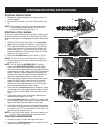
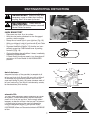
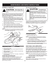
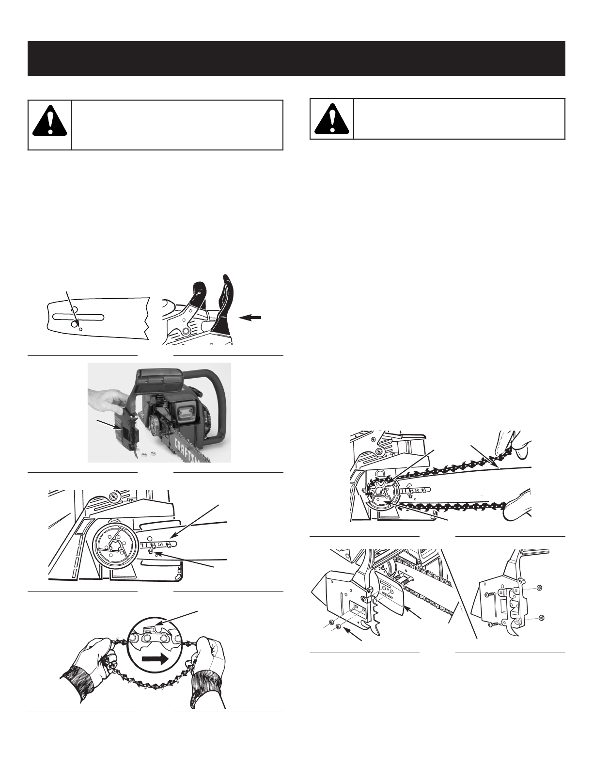
REMOVING GUIDE BAR AND CHAIN
NOTE: Always wear heavy gloves when handling the
saw chain.
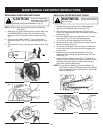
1. Make sure the Chain Brake® lever is pulled back into
the DISENGAGED position (Fig. 21). Remove bar
retaining nuts with supplied multi-purpose tool (Fig.
22).
2. Remove chain brake cover (C, Fig. 22) and outer
guide bar plate (I, Fig. 27) by pulling straight out (Fig.
22).
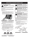
3. Slide bar off the two bar bolts and remove chain (Fig.
23).
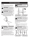
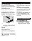
REPLACING GUIDE BAR AND CHAIN
1. Spread chain out in a loop with cutting edges (E)
pointing CLOCKWISE around loop (Fig. 24).
2. Slip the chain around the sprocket (F) behind the
clutch (G). Make sure the links fit between the sprock-
et teeth (Fig. 25).
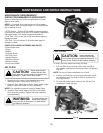
3. Place the slotted end of the guide bar over the two
bar bolts (D, Fig. 23). Be sure adjusting tang
(J, Fig. 23) is in lower adjusting hole of the bar.
4. Guide the drive links into the groove (H) and around
the end of the bar (Fig. 25).
5. The chain will be tight so you will have to rotate the
clutch clockwise by hand so the chain engages the
bar sprocket.
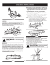
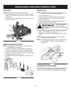
6. Replace the outer guide bar plate (I) so the bent
edges (top and bottom) are directed away from the
chain (Fig. 27).
7. Install the Chain Brake® cover (Fig. 27). Make sure
the chain does not slip off of the bar. Install the 2 bar
retaining nuts hand tight and follow instructions in
Saw Chain Tension Adjustment.
NOTE: The guide bar retaining nuts are installed only
hand tight at this point because saw chain adjust-
ment is required. Follow instructions in Saw Chain
Tension Adjustment.
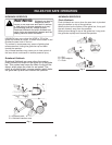
Always use protective
gloves when handling
the saw chain.
WARNING:
To ensure the bar and
chain receive oil, ONLY
USE THE ORIGINAL STYLE BAR with the oil
passage hole (A) as illustrated in Fig. 21.
CAUTION:
E
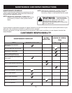
MAINTENANCE AND REPAIR INSTRUCTIONS
A
D
Fig. 21
Fig. 22
Fig. 23
H
I
G
Fig. 25
Fig. 27
B
C
Fig. 24
F
16
J
B