


Pin
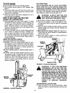
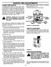
FIGURE 4.
Reservoir
Tank
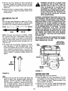
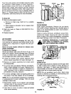
FIGURE 5.
Control
Valve
Hose
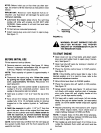
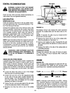
FIGURE 6.
Cotter
Return
Pressure
Hose
Pump
Suction
Hose
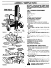
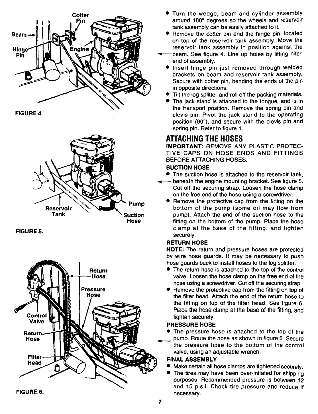
• Turn the wedge, beam and cylinder assembly
around 180° degrees so the wheels and reservoir
tank assembly can be easily attached to it.
• Remove the cotter pin and the hinge pin, located
on top of the reservoir tank assembly. Move the
reservoir tank assembly in position against the
-,i----beam. See figure 4. Line up holes by lifting hitch
end of assembly,
• Insert hinge pin just removed through welded
brackets on beam and reservoir tank assembly.
Secure with cotter pin, bending the ends of the pin
in opposite directions.
• Tilt the tog splitter and roll off the packing materials.
• The jack stand is attached to the tongue, and is in
the transport position. Remove the spring pin and
clevis pin. Pivot the jack stand to the operating
position (90°), and secure with the clevis pin and
spring pin. Refer to figure 1.
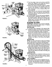
ATTACHINGTHEHOSES
IMPORTANT: REMOVE ANY PLASTIC PROTEC-
TIVE CAPS ON HOSE ENDS AND FITTINGS
BEFORE A1 I'ACHING HOSES.
SUCTION HOSE
• The suction hose is attached to the reservoir tank,
beneath the engine mounting bracket. See figure 5.
Cut off the securing strap. Loosen the hose clamp
on the free end of the hose using a screwdriver.
• Remove the protective cap from the fitting on the
bottom of the pump (some oil may flow from
pump). Attach the end of the suction hose to the
fitting on the bottom of the pump. Place the hose
clamp at the base of the fitting, and tighten
securely.
RETURN HOSE
NOTE: The return and pressure hoses are protected
by wire hose guards. It may be necessary to push
hose guards back to install hoses to the log splitter.
• The return hose is attached to the top of the control
valve. Loosen the hose clamp on the free end of the
hose using a screwdriver. Cut off the securing strap.
• Remove the protective cap from the fitting on top of
the filter head. Attach the end of the return hose to
the fitting on top of the filter head. See figure 6.
Place the hose clampat the base of the fitting, and
tighten securely.
PRESSURE HOSE
• The pressure hose is attached to the top of the
pump. Route the hose as shown in figure 6. Secure
the pressure hose to the bottom of the control
valve, using an adjustable wrench.
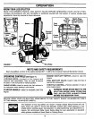
FINAL ASSEMBLY
• Make certain all hose clamps are tightened securely.
• The tires may have been over-inflated for shipping
purposes. Recommended pressure is between 12
and t5 p.s.i. Check tire pressure and reduce if
necessary.