


, iii i iiiiiii iiii iii
FLEXIBLEPUMP COUPLER
The flexible pump coupler is a nylon "spider" insert,
located between the pump and engine shaft. Over a
period of time, the coupler wil! harden and deteriorate.
Replacement is needed if you detect vibration or
noise coming from the area between the engine and
the pump. If the coupler fails completely, you wil!
experience a loss of power. For a replacement tlexible
pump coupler, order part number 717-0891.
iii ii i iii i iiiii | iiiiii in
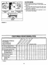
SERVICE AND ADJUSTMENTS
IIIIIII i z= m
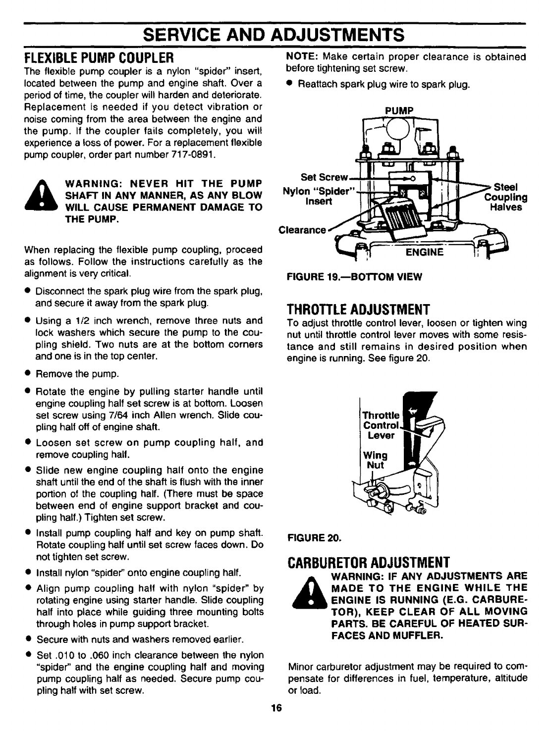
NOTE: Make certain proper clearance is obtained
before tightening set screw.
• Reattach spark plug wire to spark plug.
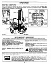
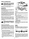
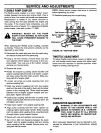
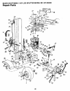
PUMP
WARNING: NEVER HIT THE PUMP
SHAFT IN ANY MANNER, AS ANY BLOW
WILL CAUSE PERMANENT DAMAGE TO
THE PUMP.
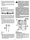
Set Screw
Nylon
Insert
piing
Halves
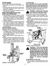
When replacing the flexible pump coupling, proceed
as follows. Follow the instructions care|ully as the
alignment is very critical.
• Disconnect the spark plug wire from the spark plug,
and secure it away from the spark plug.
• Using a 1/2 inch wrench, remove three nuts and
lock washers which secure the pump to the cou-
pling shield. Two nuts are at the bottom corners
and one is in the top center.
• Remove the pump.
• Rotate the engine by pulling starter handle until
engine coupling half set screw is at bottom. Loosen
set screw using 7/64 inch Allen wrench. Slide cou-
pling half off of engine shaft.
• Loosen set screw on pump coupling half, and
remove coupling hail.
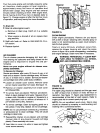
• Slide new engine coupling half onto the engine
shaft until the end of the shaft is flush with the inner
portion of the coupling half. (There must be space
between end of engine support bracket and cou-
pling half.) Tighten set screw.
• Install pump coupling half and key on pump shaft.
Rotate coupling half until set screw faces down. Do
not tighten set screw.
• Install nylon "spider" onto engine coupling half.
• Align pump coupling half with nylon "spider" by
rotating engine using starter handle. Slide coupling
half into place while guiding three mounting bolts
through holes in pump support bracket.
• Secure with nuts and washers removed earlier.
• Set .010 to .060 inch clearance between the nylon
"spider" and the engine coupling half and moving
pump coupling half as needed. Secure pump cou-
pling half with set screw.
16
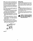
ENGINE
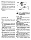
FIGURE 19.--BOTTOM VIEW
THROTTLEADJUSTMENT
To adjust throttle control lever, loosen or tighten wing
nut until throttle control lever moves with some resis-
tance and still remains in desired position when
engine is running. See figure 20.
Throttle
Control.
Lever
Wing
Nut
FIGURE 20.
CARBURETORADJUSTMENT
WARNING: IF ANY ADJUSTMENTS ARE
MADE TO THE ENGINE WHILE THE
ENGINE IS RUNNING (E.G. CARBURE-
TOR), KEEP CLEAR OF ALL MOVING
PARTS. BE CAREFUL OF HEATED SUR-
FACES AND MUFFLER.
Minor carburetor adjustment may be required to com-
pensate for differences in fuel, temperature, altitude
or load.