


7
2.2 HOURMETER
The Hourmeter tracks hours of operation for scheduled maintenance:
There will be a one time break in "CHG OIL" message that flashes with the
elapsed time in hours and tenths after the first 30 hours of operation.
This message will actually begin flashing at 29 hours and disable itself at
31 hours providing a two hour window to perform the service.
There will be a subsequent "CHG OIL" message every 100 hours. The
message will flash one hour before and one hour after each 100 hour
interval, again providing a two hour window to perform service.
Every 200 hours the "SVC" icon on the lower left hand corner of the display
will flash. The message will flash one hour before and one hour after each
200 hour interval providing a two hour window to perform service.
When the hour meter is in the Flash Alert mode, the maintenance message
will always alternate with elapsed time in hours and tenths. The hours will
flash four times, then alternate with the maintenance message four times
until the meter resets itself.
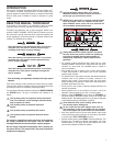
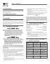
30 hours - CHG OIL — Break-in Interval (First 30 hrs only)•
100 hours - CHG OIL — Oil Change Interval (Every 100 hrs)•
200 hours - SVC — Air Filter Interval (Every 200 hrs)•
2.3 CORD SETS AND CONNECTION
PLUGS
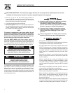
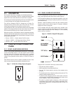
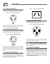
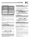
2.3.1 120 VAC, 20 AMP, DUPLEX RECEPTACLE
This is a 120 Volt outlet protected against overload by a 20 Amp push-
to-reset circuit breaker (Figure 7). Use each socket to power 120 Volt
AC, single phase, 60 Hz electrical loads requiring up to a combined
2400 watts (2.4 kW) or 20 Amps of current. Use only high quality, well-
insulated, 3-wire grounded cord sets rated for 125 Volts at 20 Amps (or
greater).
Keep extension cords as short as possible, preferably less than 15 feet
long, to prevent voltage drop and possible overheating of wires.
Figure 7 - 120 Volt AC, 20 Amp, Duplex Receptacle
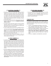
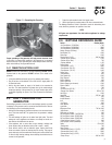
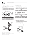
2.3.2 120 VAC, 20 AMP, GFCI RECEPTACLE
This unit is equipped with a ground fault circuit interrupter (GFCI). This
device meets applicable federal, state and local codes (Figure 8).
A GFCI receptacle is different from conventional receptacles. In the event
of a ground fault, a GFCI will trip and quickly stop the flow of electricity to
prevent serious injury.
Definition: Instead of following its normal safe path, electricity passes
through a persons body to reach the ground. For example, a defective
appliance can cause a ground fault.
A GFCI receptacle does NOT protect against circuit overloads, short
circuits, or shocks. For example, electric shock can still occur if a person
touches charged electrical wires while standing on a non-conducting
surface, such as a wood floor.
Figure 8 - 120 VAC, 20 Amp GFCI Receptacle
Testing the GFCI: Test the GFCI outlet every month as follows:
Plug a test lamp into the receptacle.•
Start the generator, the test lamp should be on.•
Press the “Test” button located on the front of the receptacle to trip •
the device.
This should stop the flow of electricity making the lamp shut off. The •
yellow trip indicator should now be on.
To restore the flow of electricity, press the “Reset” button on the front •
of the receptacle. If the GFCI does not perform in this manner, do not
use the receptacle. Contact a local service dealer.
This outlet is protected against overload by a 20A push-to-reset •
circuit breaker. Use the outlet to power 120V AC, single-phase, 60 Hz,
electrical loads requiring up to a combined 2400 watts (2.4 kW) or 20
amps of current.
7
Section 2 – Operation