


4
1.1 UNPACKING
Set the palleted carton on a rigid flat surface.•
Remove staples along bottom of carton that fasten carton to pallet. •
Open carton from top.
Remove all packaging material.•
Remove separate accessory box.•
Lift carton off the generator.•
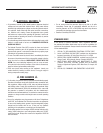
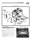
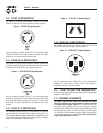
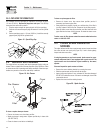
Remove generator from shipping pallet by removing bolts through the •
shipping brackets (Figure 1).
Figure 1 - Bracket Removal
1.1.1 ACCESSORY BOX
Check all contents. If any parts are missing or damaged locate an
authorized dealer at 1-888-436-3722.
Contents include:
Wheel Axle • Bolt-on tubular handle•
2 – Washers • 2 – Pneumatic Wheels•
2 – Wheel Spacers • 2 – Axle Bracket Assemblies•
2 – Cotter Pins • Bolt-on Foot•
2 – Spark Plugs • Spark Plug Wrench•
Air Filter • Oil Filter•
Pre-cleaner • Battery Charge Cable•
6 – Carriage Bolts, Washers, • Nuts
1.2 ASSEMBLY
The generator requires some assembly prior to using it. If problems arise
when assembling the generator, please call the Generator Helpline at
1-888-436-3722.
1.2.1 ASSEMBLING THE WHEEL KIT
The wheel kit is designed to greatly improve the portability of the
generator. A socket wrench with a 9/16” socket, a 1/2” socket, a 1/2”
wrench and a pair of pliers are the tools that will be needed for assembly
of the wheel kit.
NOTE:
The wheel kit is not intended for over-the-road use.
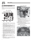
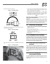
Refer to Figure 2 and install the wheel kit as follows:•
Place the generator on a hard flat surface.•
Stand at the engine end of the unit and gently tilt the generator forward, •
high enough to place wooden blocks beneath the cradle. This will allow
space to install the wheel assemblies.
Attach an axle bracket assembly with attached sleeve to either side of •
the frame. Ensure the sleeve faces outward.
Slide the axle through the sleeves on the axle brackets.•
Slide one wheel with flat washer to the outside and a spacer to the •
inside onto each end of the axle. Make sure the air inflation valve on
the wheel is facing outward.
Insert retaining pins and using pliers, bend out the ends to prevent the •
pins from falling out of the axle. Remove the wooden blocks.
1.2.2 ASSEMBLING THE HANDLE
Attach the handle by aligning one side of the handle on the cradle, then •
spread the handle around the cradle and let it spring into place. Secure
the handle to the frame using the 5/16’ hex head bolts provided. Check
each fastener to ensure that it is secure.
Using the handle, lift the unit high enough to place wooden blocks •
under the unit. Attach the front support foot to the underside of the
cradle using the 3/8” carriage bolts provided.
Remove the shipping brackets from the cradle, if it has not already •
been done.
4
Section 1 – General Information
Shipping
Bracket (x4)